
Subscribe to Our Youtube Channel
Summary of Contents for David Golf Easy Picker BALL DISPENSER
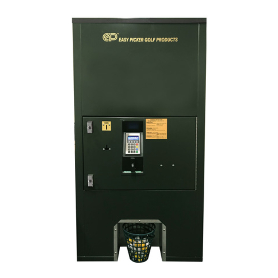
- Page 1 Easy Picker BALL DISPENSER User Manual KEEP THIS DOCUMENT WITH MACHINE FOR FUTURE REFERENCE 1300 790 890 1300 790 890 www.davidgolf.com.au www.davidgolf.com.au...
- Page 2 David Golf & Engineering Pty Ltd A.C.N 055 981 489 A.B.N 85 260 948 796 Email: dge@davidgolf.com.au Head Office Melbourne PO Box 330 OAKLEIGH VIC 3166 Ph: 03 9542 0222 Fax: 03 9540 0909 1300 790 890 www.davidgolf.com.au...
-
Page 3: Table Of Contents
Table of Contents Introduction Specifications Warranty Policy Inspection Installation Ball Adjustment Operating Instructions Periodic Inspection and Maintenance Troubleshooting List of Figures Figure 4: Ball Dispenser Assembly (2010-Present) Figure 5: Ball Dispenser Assembly Range Express (2010-Present) Figure 6: Electrical Panel Assembly (2010-Present) Figure 7: Ball Drop Mechanism Manual Figure 8: Ball Drop Lever Assembly Figure 9: Ball Drop Mechanism Assembly... -
Page 4: Specifications
Introduction Welcome to the Easy Picker family. We know you’ll find our equipment to be of the highest quality. We are sure you will enjoy many seasons of reliable use. Easy Picker’s ball dispenser is designed to be low maintenance and is manufactured at our own facility to ensure utmost quality. The Easy Picker ball dispenser is constructed of heavy-duty steel. -
Page 5: Installation
Warranty Easy Picker Golf Products, Inc., warrants this product against defects in material and workmanship for a period of ONE YEAR from the date of purchase. This warranty EXCLUDES any malfunction or dam- age due to abnormal use of the product or product operation not in compliance with the OPERATING INSTRUCTIONS section of this manual. - Page 6 Dispenser ball count adjustment- 25 To 50 Balls ( Dispenser built 2010 to Present) - Quantity can be adjusted anywhere between 25 to 50 balls - Using a 3/8” socket or wrench loosen top nuts and adjust to desire amount, then tighten nuts 1300 790 890 www.davidgolf.com.au...
-
Page 7: Operating Instructions
Operating Instructions Place range ball pail under ball dispenser delivery and test ball dispenser by inserting token, coin, cred- it card or pin numbers if using Range Express as applicable. Wait until all range balls are delivered and remove range ball pail. Verify ball dispenser’s ball-dump tray has refilled. -
Page 8: Table 1: Inspection Guide 1
Table 1: Inspection Guide 1 Inspection Interval Inspection Point Inspection Procedure and Service Daily Cabinet Exterior Check exterior for evidence of physical damage, loose hardware or input power connection. Tighten and/ or repair asnecessary. Open hopper door and inspect for any Cabinet Interior foreign debris. -
Page 9: Figure 4: Ball Dispenser Assembly (2010-Present)
FIGURE 4: BALL DISPENSER ASSEMBLY 2010 TO PRESENT Item Part No. Description BD-T154 Door, electronic mechanism BD-092 Control board, actuator BD-363 Bracket, control board BD-374 Lock-lock assembly BD-375 Coin box, plastic BD-377 Bracket, plastic coin box BD-360 Panel, electrical assembly BD-T112 Lid, front BD-053... -
Page 10: Figure 5: Ball Dispenser Assembly Range Express
FIGURE 5: BALL DISPENSER ASSEMBLY RANGE EXPRESS 2010 TO PRESENT Item Part No. Description BD-374 Lock T-lock assy BD-375 Coin box BD-377 Bracket, coin box RE-123 Card, reader itech RE-126 Transmitter with keypad assembly BD-112 Coin mechanism electronic 12v. BD-360 Panel, electrical assembly, see fig 6 BD-053 Pneumatic spring... - Page 11 FIGURE 6: ELECTRICAL PANEL ASSEMBLY 2010 TO PRESENT Item Part No. Description BD-358 Bracket, GFI, power supply CALL Fitting, heyco ½” HA-67 Box, electrical junction 2x4 HA-48 Switch, GFI BD-300 Cover, GFI weatherproof BD-282 Surge, protector 120v BD-357 Power, Supply 12v HA-69 Cord, 8ft male 1300 790 890...
-
Page 12: Figure 7: Ball Drop Mechanism Manual
FIGURE 8: (Next Page) FIGURE 7: BALL DROP MECHANISM MANUAL Item Part No. Description BD-035 Bumper pad, shuttle Call Lever pin w/ cotter pin BD-084 Bearing, shaft 1300 790 890 www.davidgolf.com.au... -
Page 13: Figure 8: Ball Drop Lever Assembly
FIGURE 8: BALL DROP LEVER ASSEMBLY Item Part No. Description BD-149 Bracket, left dump tray BD-O84 Bearing, shaft BD-105 Lever, manual dispenser Call Bolt ½”-20 x 2 ¼” Call Bolt ¼”-20 x 5/8” Call Flat washer ¼” Call Nut ¼”20 Call Nut ½”-20 Call... -
Page 14: Figure 9: Ball Drop Mechanism Assembly
FIGURE 9: BALL DROP MECHANISM ASSEMBLY 2010 TO PRESENT Item Part No. Description BD-386 Tray, dump frame 25-50 ball BD-T200 Tray, dump 25-50 ball BD-089 Actuator, Motor 12 volt BD-T101 Bracket, bearing right BD-364 Bracket, bearing, actuator BD-084 Bearing, shaft BD-032L Bracket, ball adjuster left BD-032R... - Page 15 FIGURE 10: WIRING 120 VAC TO 12 VDC 2010 TO PRESENT 1300 790 890 www.davidgolf.com.au...
-
Page 16: Figure 11: Wiring Harness
FIGURE 11: WIRING HARNESS 2010 TO PRESENT 1300 790 890 www.davidgolf.com.au... -
Page 17: Troubleshooting
Troubleshooting Any evidence of malfunction, however minor in character, should be investi-gated and corrected be- fore it develops into a major fault which may disable the Ball Dispenser for lengthy and costly repairs. Troubles most likely to be encountered, their probable cause and remedy are listed in the following Table: WARNING ENSURE ELECTRICAL POWER HAS BEEN DISCONNECTED BEFORE PERFORMING ANY... - Page 18 PROBLEM PROBABLE CAUSE REMEDY There is a green LED on GFI Power supply disconnected Reconnect power supply. switch but there is no power from GFI. at power supply 12vdc Defective power supply. Replace power supply. Obstruction in hopper Remove obstruction. preventing range balls from entering drop mechanism.
- Page 19 Control Board Programming 10-2010 To February 2013 Located on page #8 figure #4 item #2 Bill Acceptor Instructions: Place basket in opening First insert bill(s) in acceptor Then Press selection button ball Display default view: First line: Number of tokens that have been processed Second line: Dollar amount of currency that has been processed Note that these counts are NOT resettable Control board is factory set for:...
- Page 20 Electronic Mechanism Coin Programming Xeptors COIN LEARN PROCEDURE Slide the front cover up and identify the three controls to be used in this procedure: The “test” push button near center bottom. (used to input the number of credit pulses) 16 position rotary switch to the right of the push-button. (#0 is normal RUN position, #1-#6 are for learning each of 6 possible coin types that can be accepted) LED indicator half way up on the right side.
- Page 21 FIGURE 16: TROUBLESHOOTING TEST PUSH BUTTON ROTARY SWITCH If LED is flashing RED to GREEN in the “O” position turn off power for 2 minutes. Then turn back on. This should reboot the acceptor. Check to make sure the 2 half of the ac ceptor are closed together, open the acceptor and let the spring slam it shut.
- Page 22 1300 790 890 www.davidgolf.com.au...
- Page 23 1300 790 890 www.davidgolf.com.au...
- Page 24 David Golf & Engineering Pty Ltd A.C.N 055 981 489 A.B.N 85 260 948 796 Email: dge@davidgolf.com.au Head Office Melbourne PO Box 330 OAKLEIGH VIC 3166 Ph: 03 9542 0222 Fax: 03 9540 0909 1300 790 890 www.davidgolf.com.au...
Need help?
Do you have a question about the Easy Picker BALL DISPENSER and is the answer not in the manual?
Questions and answers
Does this have Ethernet port