Advertisement
Available languages
Available languages
Quick Links
Brake
Bleeder
Drainman
Classic
Vacula Automotive Products
- a division of the CEJN Group
Hasslumvägen 33
SE-541 25 Skövde, Sweden
Bedienungsanleitung Bremsentlüfter
Operation Manual Brake Bleeder
Manuel de fonctionnement
de la valve de purge de frein
Istruzioni per l'uso relative al dispositivo
di spurgo dei freni
Manual de funcionamiento
Purgador de frenos
Bruksanvisning Bromsluftare
Bedieningshandleiding remontluchter
Manual de funcionamento do
purgador de travão
09-000-8010
Edition 1/04 - 04-02-24
Seite
Page
Page
Pagine
Página
Sida
Pagina
Pág.
3
6
9
12
15
18
21
24
1
Advertisement

Summary of Contents for Vacula Drainman Classic
- Page 1 Brake Bleeder Drainman Classic Vacula Automotive Products - a division of the CEJN Group Hasslumvägen 33 SE-541 25 Skövde, Sweden Edition 1/04 - 04-02-24 Bedienungsanleitung Bremsentlüfter Seite Operation Manual Brake Bleeder Page Manuel de fonctionnement de la valve de purge de frein Page Istruzioni per l’uso relative al dispositivo...
- Page 3 Inhaltsverzeichnis Sicherheit 1.1 Einleitung 1.2 Gefahren / Sicherheitshinweise Installation 2.1 Beschreibung 2.2 Vorbereitung Bedienung 3.1 Anwendung Störungsbehebung 4.1 Luftblatern im Vakuumschlauch 4.2 Es wird keine Flüssigkeit angesaugt 4.3 Schwache oder keine Vakuumleistung Unterhalt 5.1 Generelles 5.2 Ersatzteile 5, 27 5.3 Abfallentsorgung Anhang 6.1 Technische Daten 6.2 Lieferant/Händler...
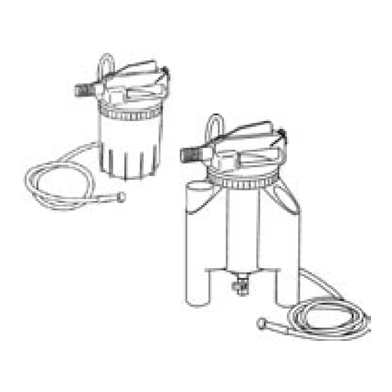
- Page 4 Installation 2.1 Beschreibung (Bild 1) a) Luftanschluss (1/4”) c) Hebelarretierung e) Sicherheitsventil b) Hebel d) Schalldämpfer 2.2 Vorbereitung Den zu Ihrem System passenden Anschlussnippel in den Luftanschluss (a) einschrauben (Dichtungsband verwenden). Sicherstellen, dass das Ablassventil geschlossen ist (nur Version Drainman). Bedienung 3.1 Anwendung Bild 2...
- Page 5 4.3 Ungenügende Saugleistung, ungenügendes Vakuum (Bemerkung: Eine merkbare Senkung des Schallpegels bestätigt, dass das volle Vakuum erreicht ist). Ist der Arbeitsdruck unter dem Minimum von 5.5 bar? Möglich durch ge knick- te oder blockierte Schläuche, schlechte Qualität von Kupplungen oder von Fittingen.
-
Page 6: Appendix 6.1 Technical Data
Contents Safety 1.1 Introduction 1.2 Warnings / Safety precautions Installation 2.1 Description 2.2 Preparation Operation 3.1 How to use Trouble shooting 4.1 Air bubbles in the vacuum hose 4.2 No fl uid drawn into canister 4.3 Slow performance / no vacuum Maintenance 5.1 General 5.2 Spare parts... - Page 7 Installation 2.1 General description (fi g. 1) a) Air inlet (1/4”) c) Lever lock e) Safety valve b) Operation lever d) Silencer element 2.2 Preparation Screw airline nipple of your quick connect coupling system into the air inlet (a). Make sure that the drain valve of the canister is closed (type Drainman only). Operation 3.1 How to use Fig.
- Page 8 4.3 Some fl uid is drawn but performance is slow / no adequate vacuum (Note: A noticeable drop in the sound level should be apparent shortly after depressing the lever. This indicates that proper vacuum is being developed). Is the working pressure below the minimum of 5.5 bar (80 psi)? Check for kinked or blocked hose, poor quality restrictive couplings or fi...
- Page 9 Table des matières Sécurité 1.1 Introduction 1.2 Avertissements / Consignes de sécurité Installation 2.1 Description 2.2 Préparation Opération 3.1 Mode d’utilisation Dépannage 4.1 Bulles d’air dans le fl exible à dépression 4.2 Aucun liquide n’est aspiré dans le bidon 4.3 Performances ralenties / absence de vide Maintenance 5.1 Généralités 5.2 Pièces de rechange...
- Page 10 Installation 2.1 Description générale (fi g. 1) a) Entrée d’air (1/4”) c) Blocage levier e) Soupape de sécurité b) Levier de commande d) Elément silencieux 2.2 Préparation Vissez le raccord de conduite d’air de votre système d’accouplement rapide dans l’entrée d’air (a). Assurez-vous que le clapet de vidange du bidon est fermé...
- Page 11 4.2 Aucun liquide n’est aspiré dans le bidon 1. La vis de purge est-elle bloquée par la crasse? Retirez, nettoyez et replacer la vis de purge. 2. Le véhicule est-il équipé d’une soupape sensible à la charge? Est-elle ouverte? 3. Y a-t-il du liquide dans le système? Contrôlez le niveau de liquide dans le réservoir du maître-cylindre (en cas d’utilisation du système de remplissage automatique, s’assurer que celui-ci est raccordé...
- Page 12 Indice Sicurezza 1.1 Introduzione 1.2 Precauzioni inerenti la sicurezza Installazione 2.1 Descrizione 2.2 Operazioni preliminari Funzionamento 3.1 Modo d’impiego Individuazione e riparazione guasti 4.1 Presenza di bolle d‘aria nel tubo a depressione 4.2 Il liquido non confl uisce nell’apposito contenitore 4.3 Funzionamento lento / assenza di depressione Manutenzione 5.1 Varie...
- Page 13 Installazione 2.1 Descrizione generale (fi g. 1) a) Attacco aria (1/4”) c) Dispositivo di bloccaggio leva e) Valvola di sicurezza b) Leva di comando d) Silenziatore 2.2 Operazioni preliminari Avvitare nell’attacco aria (a) il nipplo del sistema di accoppiamento rapido. Assicurarsi che la valvola di scarico della vaschetta sia chiusa (solo tipo Drain- man).
- Page 14 4.2 Il liquido non confl uisce nell’apposito contenitore La vite di spurgo è forse bloccata a causa della presenza di impurità? Estrarre, pulire e sostituire la vite di spurgo. L’automobile è dotata di una valvola di identifi cazione del carico? Aprire. E’...
- Page 15 Índice Seguridad 1.1 Introducción 1.2 Advertencias / Precauciones de seguridad Montaje 2.1 Descripción 2.2 Preparación Funcionamiento 3.1 Instrucciones para el uso Localización de problemas 4.1 Burbujas de aire en la manguera de aspiración 4.2 No se aspira líquido al depósito 4.3 Funcionamiento lento / vacío defi...
- Page 16 Montaje 2.1 Descripción general (fi g. 1) a) Toma de aire (1/4”) c) Bloqueo por palanca e) Válvula de seguridad b) Palanca d) Silenciador 2.2 Preparación Monte la boquilla roscada del tubo de aire del sistema de acoplamiento rápido en la toma de aire (a). Compruebe que la válvula de descarga del depósito está...
- Page 17 4.2 No se aspira líquido al depósito 1. El tornillo de purga está obstruido por suciedad. Extraiga el tornillo, límpielo y vuelva a montarlo. 2. El vehículo está equipado con una válvula sensible a la carga. Compruebe que la válvula está abierta. 3.
- Page 18 INNEHÅLL Säkerhet 1.1 Introduktion 1.2 Varnings - och säkerhetsföreskrifter Installation 2.1 Beskrivning 2.2 Förberedelser Användning 3.1 Så här gör man Felsökning 4.1 Luftbubblor i vakuumslangen 4.2 Ingen vätska sugs in i behållaren 4.3 Dålig sugeffekt / inget vakuum Underhåll 5.1 Allmänt 5.2 Reservdelar 20,27 5.3 Deponering av bromsvätska...
- Page 19 Installation 2.1 Allmän beskrivning (fi g. 1) a) Luftanslutning (1/4”) c) Handtagsspärr e) Säkerhetsventil b) Manöverhandtag d) Ljuddämparelement 2.2 Förberedelser Montera en anslutningsnippel som passar använt snabbkopplingsystem i luftanslutningen (a). Kontrollera att behållarens avtappningsventil är stängd (bara för typ Drainman). Operation 3.1 Så...
- Page 20 4.3 Vätska syns i slangen men sugeffekten verkar dålig. Apparaten verkar ej utveckla tillräckligt vakum. En märkbar minskning av ljudnivån indikerar att full vakumeffekt uppnåtts. Förekommer strypning i tryckluftsystemet som gör att arbetstrycket vid luftaren sjunker under tillåtna 5,5 bar? Kontrollera kompressor, slangar (tillräcklig innerdiameter) och använda kopplingar och ersätt vid behov.
- Page 21 Inhoud Veiligheid 1.1 Inleiding 1.2 Waarschuwingen / Veiligheidsmaatregelen Installatie 2.1 Beschrijving 2.2 Voorbereiding Werking 3.1 Hoe te gebruiken Wat te doen bij problemen 4.1 Luchtbellen in de vacuümslang 4.2 Er wordt geen vloeistof in de bus gezogen 4.3 Langzame werking / Geen vacuüm Onderhoud 5.1 Algemeen 5.2 Reserveonderdelen...
- Page 22 Installatie 2.1 Algemene beschrijving (fi g. 1) a) Luchtinlaat (1/4”) c) Hendelgrendel e) Veiligheidsventiel b) Bedieningshendel d) Dempend element 2.2 Voorbereiding Schroef de leidingnippel van het snelkoppelingsysteem in de luchtinlaat (a). Zorg ervoor dat het aftapventiel van de bus gesloten is (enkel type Drainman). Werking 3.1 Hoe te gebruiken Fig.
- Page 23 4.2 Er wordt geen vloeistof in de bus gezogen 1. Is de ontluchtingsschroef geblokkeerd door vuil? Schroef de ontluchtings- schroef eruit, maak hem schoon en zet hem er weer in. 2. Is de auto uitgerust met een belastinggevoelig ventiel? Zorg ervoor dat dit open is.
- Page 24 SUMARIO Segurança 1.1 Introdução 1.2 Advertências / Precauções de segurança Instalação 2.1 Descrição 2.2 Preparação Funcionamento 3.1 Como usar Eliminação de avarias 4.1 Bolhas de ar na mangueira de vácuo 4.2 O fl uido não é puxado para o recipiente 4.3 Desempenho lento / não existe vácuo Manutenção 5.1 Generalidades...
- Page 25 Instalação 2.1 Descrição geral (fi g. 1) a) Admissão de ar (1/4”) c) Bloqueio da alavanca e) Válvula de segurança b) Alavanca de comando d) Elemento do silenciador 2.2 Preparação Aparafuse o niple da linha de adução do ar do seu sistema de acoplamento de ligação rápida na admissão de ar (a) Certifi...
- Page 26 4.2 O fl uido não é puxado para o recipiente 1. O parafuso de purga está bloqueado pela sujidade? Remova, limpe e substitua o parafuso de purga. 2. O carro está equipado com uma válvula sensível á carga? Certifi que-se de que está...
- Page 29 Spare Parts 12-018-7001 Silencer complete 12-018-7002 Silencer elements (5x) Coupling complete (not sold separately) 12-018-0926 Safety valve complete 12-018-7021 Canister seal (3x) 12-018-7003 Overfill protection valve Valve complete (not sold separately) 12-018-0900 Universal adapter 12-018-7000 Seal-kit (incl. pos. 2, 5, 7, 8, all o-rings) 12-018-7020 Repair-kit (incl.
- Page 30 6.2 Supplier / Distributor...
Need help?
Do you have a question about the Drainman Classic and is the answer not in the manual?
Questions and answers