Table of Contents
Advertisement
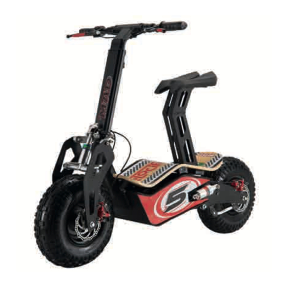
ELECTRIC VEHICLE - M AD VELoCIfERo
We want to thank you for choosing one of our products.
In this manual you have entered all the information our engineers have
deemed useful for the proper use of the MAD. It also contains the rules
for periodic maintenance that will help maintain the MAD in perfect
working order.
MAD each has a copy of the booklet.
The content of the booklet is not binding.
The manufacturer reserves the right to change data and technical fea-
tures of this model at any time and without notice, so it is not required to
promptly update the booklet itself.
MAIWAY INDUSTRY Co. Ltd
No. 547 fennan Road, Jiaojiang
District, Taizhou City, China
Advertisement
Table of Contents

Summary of Contents for MAIWAY MAD VELOCIFERO
- Page 1 The manufacturer reserves the right to change data and technical fea- tures of this model at any time and without notice, so it is not required to promptly update the booklet itself. MAIWAY INDUSTRY Co. Ltd No. 547 fennan Road, Jiaojiang District, Taizhou City, China...
- Page 2 IMPoRTANT INTRoDUCTIoN The MAD is a mode of transport that is envi- ronmentally friendly, because it does not pollute and is not noisy. The MAD implies a daily expenditure of a few cents and it is easy to carry thanks to its folding mechanism fast.
- Page 3 INfoRMATIoNS REMEMBER THAT and / or death. The MAD in your possession is not a toy, you must use it with compe- MANUAL tence, attention and respect for The manual must be read care- others and for yourself. fully before by an adult, who must Always use the recommended inform and educate the child to the clothing, helmet (fastened), glas-...
-
Page 4: Cap
INfoRMATIoNS The data and characteristics indi- cated in this handbook are not binding MAIWAY INDUSTRY Co. Ltd. reserves the right to make changes to its products at any time. -
Page 5: Table Of Contents
INfoRMATIoNS Symbols ............6 Scheduled Maintenance ......33 Generality ............6 Vehicle Disposal ........34 Safety, tips and recommendations ..7 Battery Disposal ........34 Eco-driving ..........12 Appropriately clothing ......34 CAP . 1 KNoWLEDGE of THE VEHICLE CAP . 4 ADJUSTMENTS Main elements .........14 Adjusting the front brake ......36 Contents of the box .........16 Adjusting the rear brake ......37 Commands ..........17... -
Page 6: Symbols
INfoRMATIoNS SIMBoLS GENERALITY CAUTIoN • This manual is Your guide to the Any operation by unauthorized SAfETY / WARNING use and simple maintenance of personnel, technical modifications Not comply with the notes marked the MAD. and / or alterations that are made with this symbol could result in to MAD during the warranty period, •... -
Page 7: Safety, Tips And Recommendations
INfoRMATIoNS SAfETY, TIPS AND bility of special equipment and • If you wear prescription glasses RECoMMENDATIoNS technical expertise. Therefore we you check by an adult their cle- recommend you contact a spe- anliness and suitability of their use • facts teach the proper use of your cialized workshop. - Page 8 INfoRMATIoNS Always tell an adult to • When parties make sure there • When the MAD is stopped on the every single flaw you are people nearby, and that stand, the vehicle must be turned encounter while driving; children, if present, are kept at off.
- Page 9 INfoRMATIoNS Guide always firmly grasping • This is a product ELECTRIC! Prevent • Always ride at a speed as to allow the handle with both hands the electrical and electronic you to stop safely. on the side knobs, according components coming into con- •...
- Page 10 INfoRMATIoNS • Slow before facing and closing oN THE VEHICLE NoT BRING • Do not leave it unattended if the journey of curves and varia- • Do not wear loose clothing, scar- nearby there may be small tions of soil type. ves, necklaces or other objects children.
- Page 11 INfoRMATIoNS Use the MAD only: • Get off the vehicle during move- • Driving while intoxicated or under • When a responsible adult has ment. the influence of drugs or medici- suitably informed you on the nes that may decrease the rate •...
-
Page 12: Eco-Driving
INfoRMATIoNS ECo-DRIVING • If you have full control of the • In the absence of people or ani- vehicle even when stationary and mals that you can not get under The noise and the pollution can firmly place both feet on the control the position or that may produced by each vehicle ground while comfortably sitting... - Page 13 CHAPTER 1: KNoWLEDGE of THE VEHICLE ToPIC INDEX MAIN ELEMENTS BoX CoNTENTS CoMMANDS TECHNICAL DATA WIRING DIAGRAM...
-
Page 14: Main Elements
CHAPTER 1: KNoWLEDGE of THE VEHICLE MAIN ELEMENTS Key switch Height adjustment handlebar Throttle grip Rear brake lever front brake lever Handlebar lock lever footboard front shock absorber Rear shock absorber Seat front brake caliper front brake caliper frame handlebar Drive chain Seat height adjustment Adjusting clearance of the handlebars... -
Page 15: Contents Of The Box
CHAPTER 1: KNoWLEDGE of THE VEHICLE CoNTENTS of THE BoX Your MAD is contained in the box of size 1350 x 350 x 570 mm. Inside contains the following components: 1. MAD 500 - 500W 36V o MAD 800 - 800W 36V o MAD 1000 - 1000W 48V o MAD 1300 - 1300W 48V o MAD 1600 - 1600W 48V... -
Page 16: Commands
CHAPTER 1: KNoWLEDGE of THE VEHICLE CoMMANDS Throttle grip front brake lever Rear brake lever... -
Page 17: Technical Data
CHAPTER 1: KNoWLEDGE of THE VEHICLE TECHNICAL DATA Charging time • MAD 500 - 800 ..........4-6 h Vehicle weight in running order (with battery) • MAD 1000 ............6-8 h • MAD 500 - 800 ..........44 kg •... -
Page 18: Wiring Diagram
CHAPTER 1: KNoWLEDGE of THE VEHICLE WIRING DIAGRAM Legenda 1 Generatore 2 Bobina A.T. 3 Candela 4 Pulsante arresto motore Marrone Nero... - Page 19 CHAPTER 2: ASSEMBLY of VEHICLE ToPIC INDEX oPENING of THE HANDLEBAR PoSITIoNING KNoBS oN THE HANDLEBAR HEIGHT ADJUSTMENT of THE HANDLEBAR ACCESS AND ACTIVATIoN BATTERY AND ENGINE MoUNTING SADDLE...
-
Page 20: Opening Of The Handlebar
CHAPTER 2: ASSEMBLY of VEHICLE oPENING of THE fig. A HANDLEBAR The MAD is shipped folded with the handlebars disassembled (fig. A). Unscrew the nut 1 and remove the screw 2 (fig. B). fig. B Place the handlebar and insert the screw 2 with locking nut 1 (fig. -
Page 21: Positioning Knobs On The Handlebar
CHAPTER 2: ASSEMBLY of VEHICLE PoSITIoNING KNoBS oN THE HANDLEBAR After positioning the handlebar in a vertical position, the knobs of the handlebar have suspended as shown in fIG. Grasp the control group left (rear brake), turn it horizontally and pull the bushing out. -
Page 22: Height Adjustment Of The Handlebars
CHAPTER 2: ASSEMBLY of VEHICLE HEIGHT ADJUSTMENT of THE HANDLEBAR By turning the knob indicated and turning counterclockwise you can adjust the handlebar height by raising or lowering. When the adjustment has been made tighten the knob by turning clockwise. Make sure the handlebar is tight. - Page 23 CHAPTER 2: ASSEMBLY of VEHICLE ACCESS AND ACTIVATIoN BATTERY AND ENGINE The battery and the engine are already positioned on MAD. To access the battery and to the motor is necessary to raise the platform, as shown in fIG. To activate the electric circuit insert the fuse supplied kit.
-
Page 24: Mounting Saddle
CHAPTER 2: ASSEMBLY of VEHICLE MoUNTING SADDLE Enter the full frame of the saddle fig. A fig. B on the bush hole steering it into the groove (fig. A). once you positioned the saddle screw the two knobs (one for side) provided until no play (fig. -
Page 25: Operation And Control Vehicle
CHAPTER 3: oPERATIoN AND CoNTRoL VEHICLE ToPIC INDEX BATTERY CHARGING STARTING THRoTTLE CoNTRoL AND fRoNT BRAKE REAR BRAKE CoNTRoL BRAKING SYSTEM MAINTENANCE, GENERALITY MAINTENANCE AND CHECKS To BE CARRIED CHECKS AfTER CLEANING SCHEDULED MAINTENANCE VEHICLE DISPoSAL SBATTERY DISPoSAL APPRoPRIATE CLoTHING... -
Page 26: Battery Charging
CHAPTER 3: oPERATIoN AND CoNTRoL VEHICLE BATTERY CHARGING - once attached, the charger has a little red indicates that the loading The MAD comes already loaded but process. When the light turns red it is recommended to charge for at and green you can unplug the least 6-8 hours before use. -
Page 27: Starting
CHAPTER 3: oPERATIoN AND CoNTRoL VEHICLE STARTING Insert the key into the ignition switch and turn to the right. At this point the MAD is ready for use. -
Page 28: Throttle And Front Brake
CHAPTER 3: oPERATIoN AND CoNTRoL VEHICLE THRoTTLE CoNTRoL AND fRoNT BRAKE The group throttle and the rear brake is located on the right handlebar. Turn the knob 1 to increase the speed and release to decrease. Pull the lever 2 of the front brake to brake with the front wheel. -
Page 29: Rear Brake Control
CHAPTER 3: oPERATIoN AND CoNTRoL VEHICLE REAR BRAKE CoNTRoL The group rear brake is located on the left handlebar. Pull the brake lever posteirore to curb with the rear wheel. -
Page 30: Brake System
CHAPTER 3: oPERATIoN AND CoNTRoL VEHICLE BRAKING SYSTEM The MAD is equipped with a brake system front and rear mechanical disc. Are both activated by levers on the handlebars. The right lever activates the front brake, the lever of the left rear. Be sure to leave the throttle before braking. -
Page 31: Maintenance, Generality
CHAPTER 3: oPERATIoN AND CoNTRoL VEHICLE MMAINTENANCE, • Do not climb on MAD when it is and disinfected. GENERALITY on the stand. In the event of malfunctions and / or breakages on MAD immediately MAINTENANCE AND for a more efficient MAD we warned an expert. -
Page 32: Checks After Cleaning
CHAPTER 3: oPERATIoN AND CoNTRoL VEHICLE CHECKS AfTER CLEANING After cleaning the MAC is a good idea: • Lubricate the pivot points on the suspension; • Perform a perfect cleaning and drying of the chain unit - crown - pinion followed by a good grea- sing, in order to maintain as long as the good condition of these organs;... -
Page 33: Scheduled Maintenance
CHAPTER 3: oPERATIoN AND CoNTRoL VEHICLE SCHEDULED MAINTENANCE first Every Every Every pag. control 20 hours 40 hours 80 hours BATTERY BRUSHLESS MoToR BATTERY CHARGING BRAKES 30-36-37 TIRES DRIVE CHAIN GREASE AND TIGHTENING BoLTS NoTE: The symbols (C), (D), (P), respectively refer to CoNTRoL CHANGE, CLEAN. -
Page 34: Vehicle Disposal
CHAPTER 3: oPERATIoN AND CoNTRoL VEHICLE APPRoPRIATE CLoTHING VEHICLE DISPoSAL BATTERY DISPoSAL • Only after wearing clothes with Remember that the MAD The MAD is marked with the symbol long sleeves and a certain consists of materials partly of recycling on the disposal of elec- thickness. -
Page 35: Adjustments
CHAPTER 4: ADJUSTMENTS ToPIC INDEX ADJUSTING THE fRoNT BRAKE ADJUSTING THE REAR BRAKE TIGHTENING THE CHAIN ADJUSTING CLEARANCE of THE HANDLEBARS SEAT HEIGHT ADJUSTMENT... -
Page 36: Adjusting The Front Brake
CHAPTER 4: ADJUSTMENTS ADJUSTING THE fRoNT BRAKE The front brake is of the disc type with mechanical control for which requires periodic adjustment inter- ventions. The clearance on the front brake lever should be 5 to 6 mm. The adjustment must be performed as follows: - In the driving position to verify the clearance... -
Page 37: Adjusting The Rear Brake
CHAPTER 4: ADJUSTMENTS ADJUSTING THE REAR BRAKE The rear brake is disk type with mechanical control for which requires periodic adjustment inter- ventions. The clearance on the rear brake lever should be 5 to 6 mm. The adjustment must be performed as follows: - In the driving position to verify the clearance... -
Page 38: Tightening The Chain
CHAPTER 4: ADJUSTMENTS TIGHTENING THE CHAIN for a longer duration of the transmission chain should perio- dically check its tension. Always keep it clean of deposited dirt and lubricate. If the chain is too much / little ten- sioned restore proper tension by doing the following: - Loosen the nut A. -
Page 39: Adjusting Clearance Of The Handlebars
CHAPTER 4: ADJUSTMENTS ADJUSTING CLEARANCE of THE HANDLEBARS Act on the grub screw 1 entered in the seat of the handlebar to remove possible clearances. -
Page 40: Seat Height Adjustment
CHAPTER 4: ADJUSTMENTS SEAT HEIGHT ADJUSTMENT for the height adjustment of the saddle unlock the lever 1, in order to raise or lower the saddle to the desired position. once you have found the correct position lock lever 1. -
Page 41: What To Do In Case Of Emergency
CHAPTER 5: WHAT To Do IN CASE of EMERGENCY ToPIC INDEX TRoUBLE SHooTING... -
Page 42: Index
CHAPTER 5: WHAT To Do IN CASE of EMERGENCY PRoBLEM CAUSE REMEDY The engine does not start Check the connectors. The battery is not connected Recharge the battery. The battery is low Check all connectors. Electrical problem The rear wheel does not The transmission chain is broken Replace the drive chain. - Page 43 CHAPTER 5: WHAT To Do IN CASE of EMERGENCY PRoBLEM CAUSE REMEDY The covered surfaces are scope Along paths not uphill frozen battery Heat the battery. The distance traveled by a Accelerating feel a strange Tension the drive chain charge is too short noise.
-
Page 44: Alphabetical Index
ALPHABETICAL INDEX Safety, tips and Access and activation battery Generality ....6 recommendations ..7 and motor . - Page 45 ACCESSoIRES Led Speedometer Waterproof Bag Taillight Wood Box Steel Carrier Waterproof Bag Steel Carrier Double Headlight Hydraulic Brake Horn Hydraulic Brake Lithium Battery Accessoires Street Tire Bamboo Footrest...
- Page 46 ACCESSoIRES Cover MAD...
- Page 47 DIMENSIoNS...
- Page 48 NoTES Edition November 2015...
Need help?
Do you have a question about the MAD VELOCIFERO and is the answer not in the manual?
Questions and answers