
Subscribe to Our Youtube Channel
Related Manuals for NSK Megatorque M-EDC-PS1006 Series

Summary of Contents for NSK Megatorque M-EDC-PS1006 Series
- Page 1 MEGATORQUE MOTOR SYSTEM User’s Manual (EDC Driver Unit System) Optional Driver Unit with Analog Interface M-E099DC0C2-171 Document Number: C20171-01...
- Page 2 Ltd. is notified of in writing within, which comes first, one (1) year of shipment or 2400 total operation hours. NSK Ltd., at its option, and with transportation charges prepaid by the claimant, will repair or replace any product which has been proved to the satisfaction of NSK Ltd. to have a defect in material and/or workmanship.
-
Page 3: Table Of Contents
Contents 1. Introduction ------------------------------------------------------------ 1-1 2. Specifications---------------------------------------------------------- 2-1 2.1.System configuration ------------------------------------------------------------------ 2-1 2.2.Reference Number and Coding ----------------------------------------------------- 2-2 2.3.Dimension of EDC Drive Unit-------------------------------------------------------- 2-2 2.4. Functional Specifications ------------------------------------------------------------ 2-4 2.5. Specifications related to resolution ------------------------------------------------ 2-4 2.6. Control I/O Connector Specification----------------------------------------------- 2-5 2.6.1. - Page 4 (Blank Page) — ii —...
-
Page 5: Introduction
1. Introduction This manual describes an option of the Megatorque Motor System that consists of the EDC Driver Unit with the Analog Interface. Please refer to the user’s manual of the Megatorque Motor System (Document number: C20158) for other details. For your safety, please be sure to read the user’s manual thoroughly before operating the Megatorque Motor System. - Page 6 (Blank page) — 1-2 —...
-
Page 7: Specifications
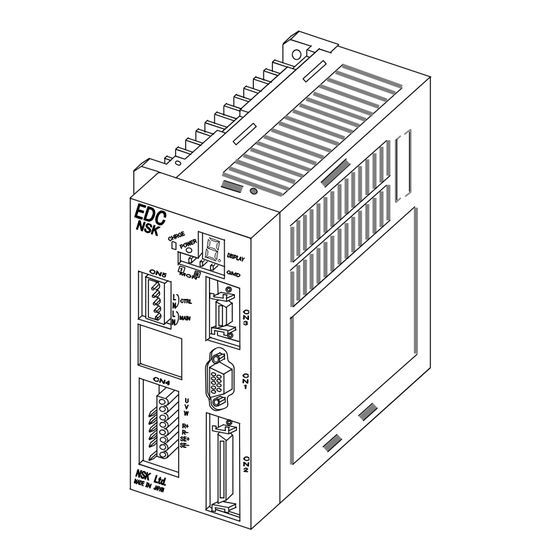
2. Specifications 2.1. System Configuration Figure 2-1: System configuration for analog command PLC* Handy Terminal 24 VDC Motor controller* power supply* HANDY TERMINAL < > EDC Driver Unit & ‘ SHIFT CTRL RS-232C communication Control IO signal Analog signal Control Main power power Megatorque Motor... -
Page 8: Reference Number And Coding
2.2. Reference Number and Coding Figure 2-2: Reference number coding of EDC Driver Unit M-EDC – PS1006 A B 5 02 – 01 No code:without connectors, blackets and manual EDC Driver Unit 01: Provide connectors, fixing Motor size code blackets and Japanese manual 02: Provid connectors, fixing Power voltage A: 200 to 230 VAC (single phase) blackets and English manual. - Page 9 Figure 2-4: Dimension of Analog input type EDC Driver Unit (same as standard type) (Motor type: PS3060, and PS3090) — 2-3 —...
-
Page 10: Functional Specifications
2.4. Functional Specifications Table 2-2: Functional Specification Control Velocity control RS-232C serial communication, Analog command:±10V mode Torque control RS-232C serial communication, Analog command:±10V Input Emergency stop, Servo-on, Stop, Clear, Over travel limit, Integration OFF Control Input signals Position feedback Refer to “2.5.Specifications related to resolution” Output Driver Unit ready, Warning, Servo-state,±Travel limit detection, signals... -
Page 11: Control I/O Connector Specification
2.6. Control I/O Connector Specifications Table 2-4:Mating connector Connector Manufacturer and model Driver Unit’s connector Molex 52986-5071 Mating connector (user’s device side) Molex 54306-5019 Mating connector shell (user’s device side) Molex 54331-0501 Use shielded cable for wiring of the CN2 connector and be sure to use twisted cables for the position feed back signals. -
Page 12: Cn2 Signal List
2.6.2. CN2 Signal List ! Caution : Follow the specification documents for the specially ordered System when its settings of Inputs and Outputs are different from the standard. ! Caution :Never connect the idle pins that are instructed as “Do not connect.” Do not disconnect the idle pins at the master controller (PLC, etc) side after you have connected all pins of the CN2 connector. - Page 13 Table 2-5 (continued): CN2 signal name and function (Shipping set) Input Signal Contact Port Signal name Function Output code code logic Output signal common – – Common for output signal. – – Output signal common Reports that the Motor is ready to rotate. DRDY Positive Driver Unit ready...
- Page 14 (Blank page) — 2-8 —...
-
Page 15: Analog Input Function
3. Analog Input function : Caution Constrain of motor speed ! ・ Each motor type has its maximum speed. Check the maximum speed in the specification sheet. ・ The parameter VL (Velocity limiter) depends on parameter FR (Feedback signal resolution). :... -
Page 16: Velocity Control Mode
3.2. Velocity Control Mode Parameter SL2 sets the control mode to velocity control. SL1: Torque control mode SL2: Velocity control mode SL3: Inhibit Velocity control via the RS-232C command or the analog command may be selected in the velocity control mode. Parameter AC selects the way of control. -
Page 17: Velocity Control With Analog Command
3.2.2. Velocity Control with Analog Command Velocity of the Motor may be directly controlled with the analog velocity command in the velocity control mode. Voltage range of the analog command is ± 10V. Offset adjustment is possible setting parameter AF. (Refer to “3.2.2.1. Offsetting Analog Velocity Command.”) Parameter AC selects the polarity of command voltage. -
Page 18: 1.Offsetting Analog Velocity Command
0 (zero). Connect the master controller and the Driver Unit, and then input analog velocity command 0 (zero). Input the password. The acknowledgement will be returned. :/NSK ON NSK ON Input as :AF/ST_ Pressing the ENT key sets the offset value automatically. The set value of AF will be on the screen. - Page 19 (5) Confirm the result and press the BS key. Otherwise the next command won’t be accepted. :RA/RP (6) Input the password. The acknowledgement will be returned. :/NSK ON NSK ON (7) Execute the following commands. Be sure to input the opposite sign as it was monitored by the RA command.
-
Page 20: Torque Control Mode
3.3. Torque Control Mode Parameter SL1 selects the torque control mode. SL1: Torque control mode SL2: Velocity control mode SL3: Inhibit Torque control via the RS-232C command or the analog command may be selected. Parameter AC selects the way of control. : Analog command invalid. -
Page 21: Torque Control With Analog Command
3.3.2. Torque Control with Analog Command You may control directly the output torque of the Motor with analog torque command in the torque control mode. Voltage of analog torque command is ± 10V. Offsetting analog command is possible setting parameter AF. (Refer to “3.3.2.1. Offsetting Analog Torque Command.” Parameter AC selects the polarity of command voltage. -
Page 22: 1.Offsetting Analog Torque Command
3.3.2.1. Offsetting Analog Torque Command You may adjust offset value of command voltage with the parameter AF. Offset adjustment of the Driver Unit has been made at the shipping. With the parameter AF, reset the offset along the master controller. Parameter AF sets the offset value by 0.3 mV per parameter data in the range of AF –6552 to AF 6552. -
Page 23: Glossary Of Commands And Parameters
4. Glossary of Commands and Parameters The password must be entered before inputting a command that is marked with AC : Analog Command Mode Format : AC data Data : -1, 0, 1 Shipping set Sets the validity (valid/invalid) and sign of the analog command input. AC0 : Analog command input invalid. - Page 24 AFP : Analog Command Filter, Primary Format : AFP data Data range1 Primary analog command filter is OFF Data range2 : 10 to 1000 [Hz] Shipping set : 200 This parameter sets the low-pass filter against the analog command. TS0 or ?AFP command reports the current setting. AFS: Analog Command Filter, Secondary Format : AFS data...
- Page 25 RA: Read Analog Command Format : RA/RP Reads an analog command value when the analog command is valid. “RA INHIBITED” message will be returned when the analog command is invalid. Adding /RP to RA command will report the reading repeatedly, while RA input alone reports in one shot.
- Page 26 (Blank page) — 4-4 —...
-
Page 27: Conformity With The International Safety Regulations
5. Conformity with the International Safety Regulations The Megatorque Motor Systems conform to the EC Directives (CE Marking) and Underwriters Laboratory (UL) regulations. 5.1. Conformity with the EC Directives The Megatorque Motor System is a machine component that conforms to provisions of the EC Low Voltage Directive. - Page 28 Conditions to Conform with EC Directives The wiring example shown below is one of our recommendations for the conformity with the EC Directives. Figure 5-1: Wiring diagram (Example) EDC Driver Unit AC power Circuit Noise breaker source filter Control power PS Series Ferrite Ferrite...
-
Page 29: Conformity With Underwriters Laboratories Standards
Table 5-2: List of recommended part Item Specification Manufacturer Remarks Single phase: EA32AC-10 Conforms to IEC regulations Circuit breaker Rated current: 15 A (Fuji Electric) and approved by UL Single phase: FN2070-10/06 Noise filter 250 VAC, 10 A (SHAFFNER) R-A-V781BWZ-4 Surge absorber –... - Page 30 (Blank Page) — 5-4 —...
- Page 31 MEGATORQUE MOTOR SYSTEM User’s Manual (EDC Driver Unit System) Analog Driver Unit with Analog Interface Document Number: C20171-01 Jun 20, 2008 1st Edition 1st Printing NSK Ltd.
- Page 32 1st Edition, 1st Printing Jun 20, 2008 Document Number: C20171-01...
Need help?
Do you have a question about the Megatorque M-EDC-PS1006 Series and is the answer not in the manual?
Questions and answers