Table of Contents
Advertisement
Quick Links
Advertisement
Table of Contents

Summary of Contents for MyFlyDream TeleFlyPro
- Page 1 MyFlyDream TeleFlyPro V1.0 www.MyFlyDream.com...
- Page 2 Notes Thank you for purchasing the MyFlyDream TeleFlyPro (hereinafter referred to as TFPro). Please follow this manual to get familiar with the TFPro and to operate it correctly. The TFPro is designed for use with RC-models only. Please use it in compliance with applicable local laws.
- Page 3 MFD TeleFlyPro is an enhance unit for MFD AAT(AutoAntennaTracker) system. The main function of TeleFlyPro is to modulate the tracking data into Video and Audio signals. These video and audio signals can be transmitted via a common Video-TX /RX module. With a V5.0 or newer AATDriver, the AAT system is able to demodulate the tracking data from the...
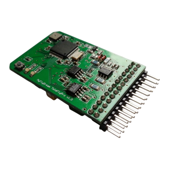
- Page 4 If you need a full-function AutoPilot device for you plane, we recommend our MFD AutoPilot product. Specification Weight Power supply 7~20V (recommended 12V) Current consume <200ma@12V(included GPS, without other electronics) 2. Wiring The picture above shows AP’s connection ports from A~J: Port Description A) Power...
- Page 5 A) Power This port supplies power to the TFPro. The TFPro has its own switching power unit so it can be powered from 7-20V. But if you want to share this power with the camera and the video transmitter, we recommend you to power the AP with a 3S lipo since most of the camera and video TX need 12V.
- Page 6 PIN#4 Power supply to camera PIN#5 Video input D) VideoTX Connect the VideoTX to this port. 插针 用途 PIN#16 PIN#17 Power supply to VideoTX PIN#18 Video output PIN#19 Audio output E) Sensors This port is for current sensor, battery voltage sensor and RSSI input. The Current sensor has a 4pin connector.
- Page 7 This port is used for the optional telemetry data radio. PIN#10 PIN#11 PIN#12 PIN#13 G) SetHome This port is for the SetHome switch. TFPro comes with a blue micro button switch. Please connect it to here. We need to use it to set “home coordinate” for the tracker. PIN#21 SetHome PIN#22...
- Page 8 3. Operating Instructions The procedure of using TFPro with your tracking system: 1). Detect the GPS baudrate. TFPro needs to recognize the GPS baudrate for the initial use. Please hold SetHome button and power on TFPro. 2 LEDs on TFPro will blink alternately. Once TFPro recognize the GPS the 2 LEDs will stay solid on.
Need help?
Do you have a question about the TeleFlyPro and is the answer not in the manual?
Questions and answers