Table of Contents
Advertisement
Quick Links
Operating Instructions
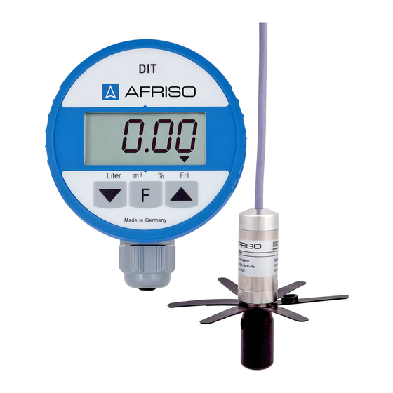
Digital Tank Contents Indicator
Type: DIT 01
DIT 01
DIT 01-E
Read instructions before using device!
Observe all safety information!
Keep instructions for future use!
Version: 05.2011 0
ID no.: 854.001.0335
Product No.: 52122
Product No.: 52123
Mess-, Regel- und
Überwachungsgeräte
für Haustechnik,
Industrie und Umweltschutz
Lindenstraße 20
DE-74363 Güglingen
Telefon: +49(0)7135-102-0
Service: +49(0)7135-102-211
Telefax: +49(0)7135-102-147
E-Mail: info@afriso.de
Internet: www.afriso.de
Advertisement
Table of Contents

Subscribe to Our Youtube Channel
Related Manuals for Afriso EURO-INDEX DIT 01-E

Summary of Contents for Afriso EURO-INDEX DIT 01-E
- Page 1 Internet: www.afriso.de Operating Instructions Digital Tank Contents Indicator Type: DIT 01 DIT 01 Product No.: 52122 DIT 01-E Product No.: 52123 Read instructions before using device! Observe all safety information! Keep instructions for future use! Version: 05.2011 0 ID no.: 854.001.0335...
-
Page 2: Table Of Contents
Contents About this manual....................4 Precautions ....................4 Explanation of symbols and typeface ............4 Safety ........................5 Intended use ....................5 Predictable incorrect application ..............5 Safe handling ....................5 Staff qualification..................6 Modifications to the product .................6 Usage of spare parts and accessories............6 Liability information ..................6 Product description....................6 Design ......................7 Scope of delivery..................8... - Page 3 11 Spare parts and accessories .................23 12 Warranty ........................23 13 Copyright .......................23 14 Customer satisfaction ....................23 15 Adresses........................24 DIT 01...
-
Page 4: About This Manual
About this manual About this manual This instruction manual is part of the product. Read this manual before using the product. Keep this manual during the entire service life of the product and always have it readily available for reference. Always hand this manual over to future owners or users of the product. -
Page 5: Safety
Safety 2 Safety Intended use The DIT 01 digital tank contents indicator is exclusively suitable for the measurement of filling levels in heating oil tanks with heights up to 3 metres. Any use other than the use explicitly permitted in this instruction ma- nual in not permitted. -
Page 6: Staff Qualification
Product description Extreme environmental conditions have negative effects on the func- tion of the product. Protect the DIT 01 from shocks. Only use the digital unit in rooms. Protect the digital unit from humidity. Staff qualification The product may only be mounted, commissioned, operated, main- tained, shut down and disposed of by qualified, specially trained staff. -
Page 7: Design
Product description metres, percentage and filling level. The device is programmed via the two keys . A lithium battery is contained in the housing of the digital unit. The battery is not connected when the device is shipped. The free end of the cable is connected to the pressure sensor. The pressure sensor and the digital unit form one unit. -
Page 8: Scope Of Delivery
Product description Scope of delivery • Digital unit • Pressure sensor with spacer • Moisture-proof junction box • Insulating screw joint, 4 poles • Wall holder for DIT 01: Screw connection DIT 01 • Connection set 2" x 1½" x 1": Flat packing NBR Adapter G1½... -
Page 9: Function
Specifications Connection DIT 01-E • Euroflex combination withdrawal fitting with 3.1 m suction tube, 2 O rings (6.5 x 1.5 mm) and pressure screw: Function The pressure sensor is located at the lowest point of the heating oil tank and transforms the hydrostatic pressure of the heating oil into an electrical signal. - Page 10 Specifications Parameter Value Resolution 14 bit Measuring input 0-3,6 V Accuracy* < ± 1,0 % FSO, IEC 60770 Operating temperature range Ambient 0 °C to +45 °C Storage -5 °C to +80 °C Electrical safety Protection IP 51 EN 60529 Electromagnetic compatibility (EMC) Noise suppression According to EN 50081-1...
-
Page 11: Approvals, Tests And Conformities
Transportation and storage Parameter Wert Storage -5 °C to +80 °C Electrical safety Protection IP 68 EN 60529 Electromagnetic compatibility (EMC) Noise suppression According to EN 50081-2 Noise immunity According to EN 50082-2 Accuracy of complete system*: < ± 1,5% FSO, IEC 60770 * With reference to the filling level indication in mm. -
Page 12: Mounting And Commissioning
Mounting and commissioning Mounting and commissioning Tank data determination Before the DIT 01 tank contents indicator is installed, you must de- termine the appropriate tank data. Please document the tank data on this page for safety reasons and to allow for subsequent checks. Tank shape Refer to the table below to find the appropriate code for the tank shape. -
Page 13: Mounting The Wall Holder
Mounting and commissioning Mounting the wall holder Use the enclosed screw (4 x 30 mm) and, if necessary, a dowel (6 mm) to mount the wall holder for the DIT 01 tank contents in- dicator at the desired location. Mounting the junction box The provided moisture-proof junction box is not suitable for exterior application. -
Page 14: Connecting The Battery
Mounting and commissioning A transparent tube can be seen at the cable end of the pressure sensor. This tube provides the pressure sensor with atmos- pheric pressure. Make sure not to close or bend this tube in or- der to avoid incorrect measurements. The junction box must be closed in such a way that it is water- tight but not completely airtight. -
Page 15: Mounting The Pressure Sensor
Mounting and commissioning display shows the arrows to indicate that you are in calibration mode. Press the keys simultaneously to correct the offset to the value 0.00. When you do this, the pressure sensor must not be in the tank. In this state, you can zero the system any number of times. - Page 16 Mounting and commissioning 12. Move the cable in the connection until the probe tip just reaches the tank bottom. The measuring hole of the pressure sensor must not be immersed in the oil sludge. The oil volume below the level of the measuring hole is not detected by the pressure sensor.
- Page 17 Mounting and commissioning 1“ thread Connections elements to fixate the cable 1½“ thread 2“ thread Fig. 8: Mounting with screw connection 15. Determine the required cable length as described above. 16. Then tighten the screw connection in such a way that the cable can no longer move and that the connection is smell-tight.
-
Page 18: Entering The Tank Data
Mounting and commissioning 18. Insert the cable of the pressure sensor into the PG connection, determine the required length as described above and fixate it in a smell-tight way. Mounting with Euroflex Lower the pressure sensor into the tank. 19. Determine the required cable length as described above. 20. - Page 19 Mounting and commissioning display show the tank shape code 0. The 0 indicates that no tank shape code has yet been selected. Use the keys to set the previously determined tank shape code (see chapter 6.1, page 12). 21. Press the F key to confirm the tank shape setting and continue with the tank volume data.
-
Page 20: Operation
Operation the tank is completely full. At levels of less than 50 %, a correction o the value indicated is not meaningful. In order to correct the curren filling level, you can overwrite the displayed value. Use the keys to set the previously determ ined filling level. -
Page 21: Subsequent Zero Balancing
Maintenance The top left corner of the display shows the symbol. Now you can either check or correct the tank data. If you do not want to change the tank data, press the F key four times in order to return to the normal measuring mode. -
Page 22: 10 Shutting Down And Disposal
Shutting down and disposal Problem Possible reason Repair Battery voltage Replace the bat- appears on the below critical va- tery (refer to chap- display. lue. ter 8.2, page 21). Display does not Battery is empty. Connect the bat- display anything. tery (refer to chap- ter 6.5, page 14). -
Page 23: Spare Parts And Accessories
Spare parts and accessories If you do not have the opportunity to dispose of the used device in accordance with environmental regulations, please contact us for possibilities to dispose of it or to return it. 11 Spare parts and accessories Part Part No. -
Page 24: Adresses
Adresses 15 Adresses The addresses of our worldwide representations and offices can be found on the Internet at www.afriso.de. DIT 01...
Need help?
Do you have a question about the DIT 01-E and is the answer not in the manual?
Questions and answers