
Summary of Contents for AerX i-Digit
- Page 1 Programmable electronic thermostat with LCD display for 2/4 pipe fan coils Installation Rel. 05_00_02 and user manual...
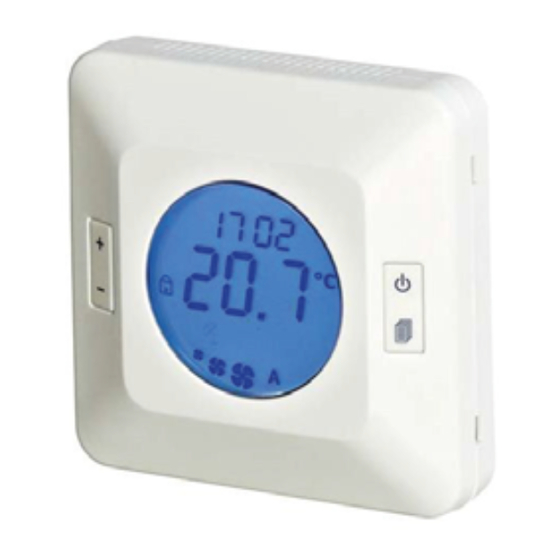
- Page 3 FUNZIONI GENERALI DEL PRODOTTO: GENERAL FUNCTIONS OF THE PRODUCT: -Termostato elettronico digitale, ampio display LCD con retroilluminazione ad intensità variabile blu GENERAL FUNCTIONS OF THE PRODUCT: -Prodotto studiato e progettato per il controllo di fan-coil (ventilconvetori) e cassette idroniche –Digital electronic thermostat, large LCD display with dimmable blue back lighting -Programmatore orario settimanale di serie –Product designed for control of fan-coil and hydronic cassettes –Digital electronic thermostat, large LCD display with dimmable blue back lighting...
- Page 4 TECHNICAL CHARACTERISTICS Power supply: 230V~ −15% +10% WATER SENSOR: 50Hz Power absorbed: 2.0 VA Sensor type: NTC 10kΩ @ 25˚C +/−1% Operation temperature: 0˚C to 40˚C Precision: +/− 1˚C Storage temperature: −10˚C to +50˚C Resolution: 0.1˚C Humidity function: 20% to 80% RH non-condensing Display field: 0˚C to 50˚C Storage humidity: 20% to 80% RH (N.C.) Cabling: max.
- Page 5 -Button (ON/OFF) -Button (ON/OFF) Press for 2 seconds to switch on or turn off the device; switched off, the thermostat shows OFF on the Press for 2 seconds to switch on or turn off the device; switched off, the thermostat shows OFF on the display but the ambient temperature, clock, any alarms and the relative humidity (optional) continue to be display but the ambient temperature, clock, any alarms and the relative humidity (optional) continue to be displayed.
- Page 6 ...
- Page 7 Select the weekday to programme and confirm it with the menu button to access programme options for the F1 and F2 bands: Press the menu button and set the hour for activation of the F1 band Press the menu button and set the minutes for activation of the F1 band Press the menu button and set the operating temperature of the F1 band Press the menu button and set the hour for activation of the F2 band Press the menu button and set the minutes for activation of the F2 band...
- Page 8 Table 4 : example programme of weekly schedule set in table 2 if P1=2 F1 Time F1 ON/OFF F2 Time F2 ON/OFF 08:00 23:00 14:00 23:00 14:00 23:00 14:00 23:00 14:00 23:00 14:00 20:00 08:00 14:00 summer winter When the icon is turned on in the display, it shows that the thermostat is following a programmed schedule.
- Page 9 Parameter configuration menu The menu for configuring parameters is divided in two levels, a first level protected from access and unintended changes and a second level with password protection. To access the first level of the parameters menu press the menu button, scroll with the + button and confirm on PAr, pressing the menu button for 5 sec the P01 parameter is displayed and with the +/- buttons it is possible to scroll through all parameters from P01 to P10.
- Page 10 VIEW OF REGULATOR AND SUB-BASE’ VIEW OF REGULATOR AND SUB-BASE’ VIEW OF REGULATOR AND SUB-BASE’ VIEW OF REGULATOR AND SUB-BASE’ VIEW OF REGULATOR AND SUB-BASE’ J1(RJ45) J1(RJ45) J1(RJ45) J1(RJ45) J1(RJ45) SIMPLIFIED INTERNAL DIAGRAM SIMPLIFIED INTERNAL DIAGRAM SIMPLIFIED INTERNAL DIAGRAM SIMPLIFIED INTERNAL DIAGRAM SIMPLIFIED INTERNAL DIAGRAM CONTROL CONTROL...
-
Page 11: Blocco Tastiera
FUNZIONI SPECIALI iDIGIT2 e iDIGIT3 SPECIAL FUNCTIONS i-Digit2 AND i-Digit3 SPECIAL FUNCTIONS i-Digit2 AND i-Digit3 L’ingresso può essere utilizzato per visualizzare una informazione dall’esterno. Per rendere attiva la funzione è necessario portare P33=1. The input can be used to display an external information. For activation of the function it is necessary to set The input can be used to display an external information. - Page 12 = VELOCITA' MASSIMA lii = VELOCITA' MASSIMA I= VELOCITA' MINIMA I= VELOCITA' MINIMA lii = VELOCITA' MASSIMA XA1 = MORSETTIERA i-Digit KA2 = RELE' ATTIVAZIONE XA1 = MORSETTIERA i-Digit KA2 = RELE' ATTIVAZIONE KA2 = RELE' ATTIVAZIONE KA2 = RELE' ATTIVAZIONE...
- Page 13 I = VELOCITA' MINIMA N = NEUTRO - 230Vac I = VELOCITA' MINIMA N = NEUTRO - 230Vac XA1 = MORSETTIERA i-Digit Il = VELOCITA' MEDIA SISTEMA 2TUBI {valvola flottante-tre punti) Il = VELOCITA' MEDIA M1 = MOTORE VENTILATORE- 230Vac...
- Page 14 CONFIGURATION INPUT J1 (RJ45) PLACED ON THE BACK OF THE REGULATOR CONFIGURATION INPUT J1 (RJ45) PLACED ON THE BACK OF THE REGULATOR CONFIGURATION INPUT J1 (RJ45) PLACED ON THE BACK OF THE REGULATOR CONFIGURATION INPUT J1 (RJ45) PLACED ON THE BACK OF THE REGULATOR CONFIGURATION INPUT J1 (RJ45) PLACED ON THE BACK OF THE REGULATOR CONFIGURATION INPUT J1 (RJ45) PLACED ON THE BACK OF THE REGULATOR CONFIGURATION INPUT J1 (RJ45) PLACED ON THE BACK OF THE REGULATOR...
- Page 15 Motor with electronic 2 pipe system 4 pipe system Motor with electronic Motor with electronic 2 tube system 2 tube system 4 tube system 4 tube system Motor with electronic 2 tube system 4 tube system Motore con controllo Motore con controllo Motore con controllo Motore con controllo Motore con controllo...
- Page 16 MENU MAP Manuale di installazione e uso - Installation and user manual | 12_05_00_02...
-
Page 17: Level 1 Parameters
DEFAULT LEVEL 1 PARAMETERS VALUE enabled with enabled with weekly programme not enabled set point ON/OFF PtaB factory customisation tables 0 .. 20 range of neutral zone (°C) 0 .. 10 type of system 2 pipe system 4 pipe system fan only fan regulation thermostated... - Page 18 fan switch-off delay with 10 .. 600 resistor OFF (sec) contact open, input window contact open, function not function active (RJ45 type connector) active DEFAULT LEVEL 2 PARAMETERS VALUE contact open, economy input contact open, function not (on J1-type RJ45) function active active contact open,...
- Page 19 NOTE Manuale di installazione e uso - Installation and user manual | 12_05_00_02...
- Page 20 12_05_00_02__IOM Manual_Neutral_i-Digit_EN...
Need help?
Do you have a question about the i-Digit and is the answer not in the manual?
Questions and answers