Table of Contents
Advertisement
Quick Links
Advertisement
Table of Contents

Related Manuals for Bsmarthome SH-01 Series

Summary of Contents for Bsmarthome SH-01 Series
- Page 1 SH-01-002 Installation Guide...
-
Page 2: Table Of Contents
TABLE OF CONTENTS Introduction ............4 Getting Started ..............5 Installing the Thermostat ..........6 Disassembly ... - Page 3 Standard Heat-Cool, 2 speed fan O/B = 'B'..… …..16 Standard Heat-Cool, 2 speed fan O/B = 'O'.....17 Standard Heat Pump, 1 speed fan O/B = 'B'..18 Standard Heat Pump, 1 speed fan O/B = 'O'.
-
Page 4: Introduction
Specifications ............29 INTRODUCTION The SH-01 SERIES is a feature-rich touchscreen thermostat that can be powered or hardwired to the HVAC equipment. Using a common sense approach to the installation will ensure this product is installed properly and to the customer’s satisfaction. -
Page 5: Getting Started
As with any HVAC project, careful installation is the key to a successful outcome. Time taken during the installation process will be rewarded with fewer call-backs. The steps required to install the SH-01 SERIES thermostat are as follows. 1. Read and understand this Installation Manual and User Manual. -
Page 6: Installing The Thermostat
INSTALLING THE THERMOSTAT DISASSEMBLY There are two release slots located on the bottom of the thermostat. Gently push the flat blade of a small screwdriver into one slot at a time and pry upward until the catch disengages. Carefully swing the thermostat upward and away from the subbase. -
Page 7: Thermostat Location
THERMOSTAT LOCATION The SH-01 SERIES should be installed in a location that represents the ambient space temperature. Do not install the thermostat in an area where drafts are present, near the floor, behind doors or on an external wall. Avoid placing the... -
Page 8: Mounting The Subbase
MOUNTING THE SUBBASE When mounting the SH-01 SERIES subbase, be aware that drafts may travel down wall cavities and enter the back of the thermostat through the control wire hole in the wall. It is important to seal the hole to prevent any drafts that might affect the internal temperature sensor. -
Page 9: Terminal Designations
connecting pins to the terminal blocks. Use a properly sized screwdriver and back each screw terminal out (counter clockwise) before landing each wire to its dedicated terminal. Do not over tighten the terminal screws. Check to ensure that all wires are landed correctly and dressed properly to prevent any shorts. - Page 10 FAN HIGH SPEED 24 VAC Hot 24 VAC Common Outdoor Sensor Sensor Common Indoor Sensor Modbus RS485+ Modbus RS485- 10 / 31...
- Page 11 11 / 31...
-
Page 12: System Wiring Diagram
SYSTEMS WIRING DIAGRAM 12 / 31... -
Page 13: Typical System Wiring Diagrams
TYPICAL SYSTEM WIRING DIAGRAMS HEAT ONLY (ELECTRIC,GAS) 13 / 31... -
Page 14: Cool Only
TYPICAL SYSTEM WIRING DIAGRAMS COOL ONLY 14 / 31... -
Page 15: Standard Heat-Cool, 1 Speed Fan O/B = 'B
TYPICAL SYSTEM WIRING DIAGRAMS Standard Heat-Cool, 1 speed fan O/B = 'B' 15 / 31... -
Page 16: Standard Heat-Cool, 1 Speed Fan O/B = 'O
TYPICAL SYSTEM WIRING DIAGRAMS Standard Heat-Cool, 1 speed fan O/B = 'O' 16 / 31... -
Page 17: Standard Heat-Cool, 2 Speed Fan O/B = 'B
TYPICAL SYSTEM WIRING DIAGRAMS Standard Heat-Cool, 2 speed fan O/B = ' B ' 17 / 31... -
Page 18: Standard Heat-Cool, 2 Speed Fan O/B = 'O
TYPICAL SYSTEM WIRING DIAGRAMS Standard Heat-Cool, 2 speed fan O/B = ' O ' 18 / 31... -
Page 19: Standard Heat Pump, 1 Speed Fan O/B = 'B
TYPICAL SYSTEM WIRING DIAGRAMS Standard Heat Pump, 1 speed fan O/B = ' B ' 19 / 31... -
Page 20: Standard Heat Pump, 1 Speed Fan O/B = 'O
TYPICAL SYSTEM WIRING DIAGRAMS Standard Heat Pump, 1 speed fan O/B = ' O ' 20 / 31... -
Page 21: Standard Heat Pump, 2 Speed Fan O/B = 'B
TYPICAL SYSTEM WIRING DIAGRAMS Standard Heat Pump, 2 speed fan O/B = ' B ' 21 / 31... -
Page 22: Standard Heat Pump, 2 Speed Fan O/B = 'O
TYPICAL SYSTEM WIRING DIAGRAMS Standard Heat Pump, 2 speed fan O/B = ' O ' 22 / 31... -
Page 23: Selecting Programmable Or Non-Programmable Op
SELECTING PROGRAMMABLE OR NON-PROGRAMMABLE OPERATION The SH-01 SERIES thermostat provides three programming modes and can also be set to a non-programmable mode: Weekday / Weekend (5 + 2) Programming - Allows you to edit the 4 time periods for the weekday and 4 time periods for the weekend. -
Page 24: Installer Setup Menu
for 4 time periods. 24 hours mode - Every day can be edited for 4 time periods. INSTALLER SETUP MENU Entering the Installer setup Menu 01 Press the icon on the main screen. 02 On the Feature Setting page 1 , select icon to page 03 On the Feature Setting page 1 , select ‘Installation Settings’... -
Page 25: Selecting Fan Speed
HVAC system SELECTING FAN SPEED 01 On Installation Settings page ,select FAN Option 02 There are two Fan speed selection : 1-Speed/2-Speed , select which FAN speed your HVAC system are SELECTING REVERSE VALVE O/B OPTIONS 01 On Installation Settings page ,select O/B Option 02 There are two selectionS : O / B , select which your reverse valve setting is SELECTING FAN MODE OPTION... -
Page 26: Selecting Differential Option
interface. 03 Press the first column, use the icons to adjust Minimum Temperature to 5-34 C. 04 Press the second column, use the icons to adjust Maximum Temperature to 6-35C. 05 Press the icon twice to save and return to the main screen SELECTING DIFFERENTIAL OPTION This function allows you to increase the switching... - Page 27 02 Find ‘Switch Diff’, press it and enter setting interface. 03 Press the first column, use the icons to adjust value 04 Press the icon twice to save and return to the main screen 27 / 31...
-
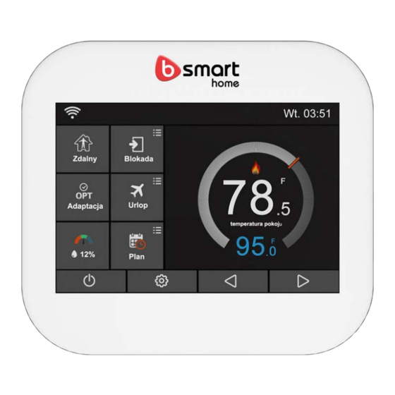
Page 28: Display Functions
DISPLAY FUNCTIONS 1, WiFi indicator- Displayed when connected to a WiFi Network 2, Hold: Temperature Hold. 3, Adjusting the optional settings. 4, Day Indicator r& Clock 28 / 31... - Page 29 5, Away: Means the SH-01 SERIES-E is maintaining a lower temperature to give frost protection. 6, Fan mode :Auto , Low ,Med ,High 7, Huimidity 1 )If humidity value less than 30%,the pointer will be in the Red area. 2) If humidity value is between 30% and 60%,the pointer will be in the Green area.
- Page 30 SPECIFICATIONS 96mm Height * 86mm Width * Dimensions 31.5mm Depth Display Resolution 480*320 Display Size 73.4 mm Height * 48.9 mm Width WIFI 802.11 b/g/n (2.4G) TOUCH Capacitive Input Voltage 24VAC, 50/60 Hz 24VAC @ 1Amp maximum per Relay Rating relay 32°...
- Page 31 41° F to 122° F Control Range 31 / 31...