
Related Manuals for ABB FAIO-01


Summary of Contents for ABB FAIO-01
- Page 1 — OPTIONS FOR ABB DRIVES, CONVERTERS AND INVERTERS FAIO-01 analog I/O extension module User's manual...
- Page 3 FAIO-01 analog I/O extension module User's manual Table of contents 1. Safety instructions 4. Installation 5. Start-up 3AUA0000124968 Rev C © 2019 ABB Oy. All Rights Reserved. EFFECTIVE: 2019-12-05...
-
Page 5: Table Of Contents
Table of contents 5 Table of contents 1 Safety instructions Contents of this chapter ............Use of warnings ................ Safety in installation ..............2 Introduction to the manual Contents of this chapter ............Target audience ................ Compatibility ................Terms and abbreviations ............3 Hardware description Contents of this chapter ............ - Page 6 6 Table of contents 6 Diagnostics Contents of this chapter ............Faults and warning messages ..........LEDs ..................7 Technical data Contents of this chapter ............Data ..................Degree of protection ............Ambient conditions ............. Package ................Hardware settings ............... A/D conversion resolution ..........
-
Page 7: Safety Instructions
Safety instructions 7 Safety instructions Contents of this chapter The chapter contains the warning symbols used in this manual and the safety instructions which you must obey when you install or connect an optional module to a drive, converter or inverter. If you ignore the safety instructions, injury, death or damage can occur. -
Page 8: Safety In Installation
8 Safety instructions WARNING! Electricity warning tells about hazards from electricity which can cause injury or death, or damage to the equipment. WARNING! General warning tells about conditions, other than those caused by electricity, which can cause injury or death, or damage to the equipment. -
Page 9: Introduction To The Manual
Introduction to the manual 9 Introduction to the manual Contents of this chapter This chapter introduces this manual. Target audience This manual is intended for people who plan the installation, install, commission, use and service the extension module. Before you do work on the module, read this manual and the applicable drive, converter or inverter manual that contains the hardware and safety instructions for the product in question. -
Page 10: Terms And Abbreviations
10 Introduction to the manual Terms and abbreviations Term Description Drive Frequency converter for controlling AC motors Electromagnetic compatibility FAIO-01 Optional analog I/O extension module... -
Page 11: Hardware Description
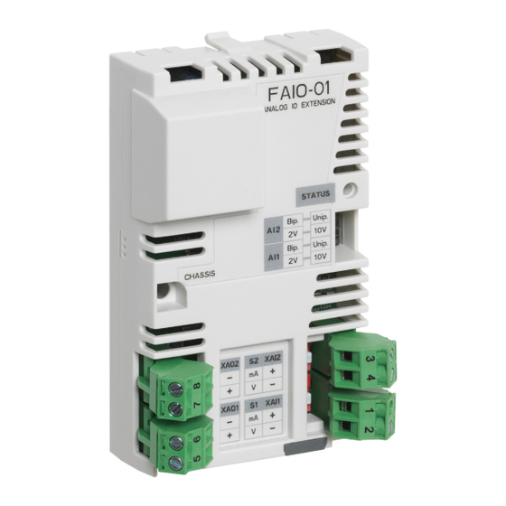
This chapter gives a short description of the extension module. Product overview The FAIO-01 analog I/O extension module expands the analog inputs and outputs of the drive control unit. It has two bipolar/unipolar current/voltage inputs and two unipolar current outputs. In the bipolar mode, the inputs can handle positive and negative signals. -
Page 12: Layout
12 Hardware description The extension module makes the signal and power connection to the drive through a 20-pin connector. ■ Layout XAI2 XAO2 XAI1 XAO1 Retaining clips Lock Mounting screw Diagnostics LED. See Diagnostics (page 23). - Page 13 Hardware description 13 DIP switches DIP switches for input mode (unipolar or bipolar) and voltage range selection DIP switch for XAI1 input signal type selection: current or voltage. DIP switch for XAI2 input signal type selection: current or voltage. Analog inputs Analog input 1 positive terminal XAI1 Analog input 1 negative terminal...
- Page 14 14 Hardware description XAI1 XAI2 Input signal Switches (4) Switches (4) range Switch S1 Switch S2 ±0 … 20 mA 0 … 2 V ±0 … 2 V 0 … 10 V ±0 … 10 V * The voltage range switches are not in use when the corresponding input is operating in the current mode.
-
Page 15: Installation
Unpacking and examining the delivery 1. Open the option package. 2. Make sure that the package contains: • FAIO-01 analog I/O extension module • this manual. 3. Make sure that there are no signs of damage. Installing the module... -
Page 16: Onto The Drive Control Unit
16 Installation injury or death, or damage damage to the equipment can occur. ■ …onto the drive control unit 1. Pull out the lock. 2. Put the module carefully into its position on the drive until the retaining clips lock it into position. 3. -
Page 17: Onto An Extension Adapter Module
Installation 17 ■ …onto an extension adapter module See FEA-03 extension adapter module user’s manual (3AUA0000115811 [English]). Selecting the input mode, voltage range and signal type Set the necessary DIP switches to applicable positions. See Layout (page 12). Use a small screwdriver. -
Page 18: General Cabling Instructions
18 Installation General cabling instructions Use 0.5 … 2.5 mm twisted pair shielded cable with an applicable voltage rating. Do not route signal cables parallel to power cables. Wiring Connect the external control cables to the applicable module terminals. ■ Connection example for motor winding temperature measurement This example shows how to connect three Pt100 sensors for motor... -
Page 19: Connection Example For External Devices
Installation 19 ■ Connection example for external devices This example shows how to connect transducers to the analog inputs and indicators to the analog outputs. FAIO XAI1+ XAO1- XAI1- XAO1+ XAI2+ XAO2- XAI2- XAO2+ Transducer 1 Transducer 2 Indicator 1 Indicator 2... -
Page 21: Start-Up
Start-up 21 Start-up Contents of this chapter This chapter contains instructions on starting up the extension module. Before you start 1. Make sure that you have set the DIP switches to applicable positions. See section Selecting the input mode, voltage range and signal type (page 17). -
Page 22: Setting The Parameters
22 Start-up Setting the parameters The extension module is started up through drive parameters. For example, in ACS880 Primary control program the parameters for I/O extension modules are located in parameter groups 14...16. For other programs, see the applicable firmware manual. ■... -
Page 23: Diagnostics
Diagnostics 23 Diagnostics Contents of this chapter This chapter shows how to trace faults with the status LEDs on the extension module. Faults and warning messages For the fault and warning messages concerning the extension module, see the drive firmware manual. LEDs The extension module has one diagnostic LED. -
Page 25: Technical Data
Technical data 25 Technical data Contents of this chapter This chapter contains the technical data of the extension module. Data ■ Degree of protection IP20 ■ Ambient conditions The applicable ambient conditions specified for the drive in its manuals are in effect. ■... -
Page 26: Hardware Settings
26 Technical data ■ Hardware settings • One DIP switch per input for selection between unipolar mode (default) and bipolar mode • One DIP switch per input for input voltage range selection • One DIP switch (S1 and S2) per input for selection between current signal (default) or voltage signal ■... -
Page 27: Analog Inputs And Outputs
Technical data 27 ■ Analog inputs and outputs Analog inputs Connector pitch 5 mm, wire size max. 2.5 mm (XAI1:+1…-2, Input ranges: (-20) 0…20 mA (default), (-2) 0…2 V, (-10) XAI2:+3…-4) 0…10 V Input impedance: 100 ohm (current), ≥ 200 ohm (voltage) Inaccuracy: ±0.2% of input and ±0.1% of Full Scale Range at 25 °C Inaccuracy for Pt100 sensors: 5 °C (9 °F) -
Page 28: Dimensions
28 Technical data Dimensions Dimensions in mm... -
Page 29: Further Information
Address any inquiries about the product to your local ABB representative, quoting the type designation and serial number of the unit in question. A listing of ABB sales, support and service contacts can be found by navigating to www.abb.com/searchchannels. Product training For information on ABB product training, navigate to new.abb.com/service/training. - Page 30 3AUA0000124968C © 2019 ABB Oy. All Rights Reserved. Specifications subject to change without notice.
Need help?
Do you have a question about the FAIO-01 and is the answer not in the manual?
Questions and answers