Table of Contents
Advertisement
Advertisement
Table of Contents
Troubleshooting

Summary of Contents for Xsensor ForeSite SS
- Page 1 User Guide...
- Page 2 ForeSite SS User Guide Revision All trademarks appearing in this document belong to XSENSOR Technology Corporation. © XSENSOR Technology Corporation. All rights reserved. The XSENSOR Pressure Imaging System is protected by copyright law. Unauthorized reproduction or redistribution of XSENSOR software is prohibited. No part of this document may be reproduced or transmitted in any form without the express written permission of XSENSOR Technology Corporation.
-
Page 3: Table Of Contents
The ForeSite SS System Overview Intended Use Product Compliance Safety Standards Emission & Immunity Standards Warnings & Cautions FORESITE SS HARDWARE ForeSite SS Tablet Wireless System ForeSite SS Tablet System Display Tablet Specifications Maintenance Storage & Transport Cleaning Cleanable Sensor Instructions FORESITE SS SOFTWARE... -
Page 5: Introduction
Introduction The ForeSite SS System Overview Intended Use Product Compliance Safety Standards Emission & Immunity Standards Warnings & Cautions... -
Page 7: The Foresite Ss System
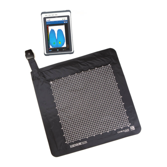
The ForeSite SS System: Overview Thank you for purchasing the ForeSite SS Pressure Imaging System! The ForeSite SS sensor is embedded with thousands of sensor cells that continuously measure the level of pressure between two solid objects. For clinical purposes, this may be the level of pressure between a wheelchair and a client’s body surface. -
Page 8: Product Compliance
Class I Medical Equipment √ Type B Applied Part. Only the sensor(s) touch the patient in normal use. The ForeSite SS is intended for use by healthcare professionals only. ForeSite SS must be installed and used as described in this user manual. Introduction... -
Page 9: Emission & Immunity Standards
Use of accessories and cables other than those provided by XSENSOR may result in increased emissions or decreased immunity. ForeSite SS complies with Part 15 of the FCC Rules. Operation is subject to the following conditions: (1) This device may not cause harmful interference, and (2) This device must accept any interference received, including interference that may cause undesired operation. - Page 10 Guidance and manufacturer’s declaration – electromagnetic emissions The ForeSite SS system is intended for use in the electromagnetic environments specified below. ForeSite SS system users should ensure that it is used in such an environment. Emissions Test Compliance Electromagnetic Environment Guidance RF emissions CISPR 11...
- Page 11 The ForeSite SS is intended for use in an electromagnetic environment in which radiated RF disturbances are controlled. The customer or the user of the ForeSite SS can help prevent electromagnetic interference by maintaining a minimum distance between portable and mobile RF communications equipment (transmitters) and the ForeSite SS as recommended below, according to the maximum output power of the communications equipment.
- Page 12 The equipment is intended for use in the electromagnetic environment specified below. The customer or the user of the equipment should assure that it is used in such an environment. Immunity IEC 60601 Compliance Electromagnetic environment - guidance test test level level Conducted 3 Vrms Portable and mobile RF communications RF IEC 150 kHz equipment should be used no closer to any part 61000-4-6 to 80 MHz of the equipment including cables, than the recommended separation distance calculated from the equation applicable to the frequency...
- Page 13 The equipment is intended for use in the electromagnetic environment specified below. The customer or the user of the Equipment should assure that it is used in such an environment. Immunity test IEC 60601 test Compliance level Electromagnetic level environment – guidance Electrostatic ±6 kV contact ±6 kV contact Floors should be discharge (ESD) ±8 kV air ±8 kV air wood, concrete IEC 61000-4-2 or ceramic tile. If floors are covered with synthetic material, the...
- Page 14 Voltage <5 % UT (>95 % <5 % UT (>95 % Mains power dips, short dip in UT) for 0,5 dip in UT) for 0,5 quality should be interruptions cycle 40 % UT cycle 40 % UT that of a typical and voltage (60 % dip in UT) (60 % dip in UT)
-
Page 15: Warnings & Cautions
Warnings & Cautions The ForeSite SS System has been designed and tested in accordance with the previously mentioned safety standards. To ensure safe use of the product, follow all safety and operating instructions in this guide. At the end of the System product life, please contact XSENSOR for safe disposal instructions (see Appendix 4). - Page 16 Warning: Do not use the equipment in the presence of a flammable anesthetic mixture with air, oxygen, or nitrous oxide. 12. Warning: Do not use the ForeSite SS Sensor to lift the client or to help remove the client from a seated position. 13.
- Page 17 Sensor against a client’s body. 23. Caution: The ForeSite SS System is designed for indoor use only. 24. Caution: For information regarding the safe disposal of the ForeSite SS Display Tablet or Sensor at the end of product life, contact a local XSENSOR representative or XSENSOR directly (see Appendix 4 of the User Guide).
-
Page 19: Foresite Ss Hardware
ForeSite SS Hardware ForeSite SS Tablet Wireless System Note: For information on using ForeSite SS ForeSite SS Tablet System Desktop Systems, please see Appendix#2. Display Tablet Specifications Power Supply Specifications X4 Lithium-Ion Battery Specifications Maintenance Storage & Transport Cleaning Cleanable Sensor Instructions ForeSite SS Label Symbols... - Page 20 ForeSite SS Hardware...
-
Page 21: Foresite Ss Tablet Wireless System
- ForeSite SS User Guide G ForeSite SS Quick Start Guide (not shown) H ForeSite SS Carry Case (not shown) * See Appendix 2 for the ForeSite SS Desktop System Set-Up Warning: To ensure operator and subject safety and compliance with regulations detailed on Page 5, connect and operate ForeSite SS only as described here. - Page 22 Set-Up Instructions Begin by ensuring both the ForeSite SS tablet and the X4 are fully charged. Recommended charge time to ensure a full charge is 2-3 hours for both devices. For the X4, connect the micro-USB on the X4 power supply to the micro-USB input on the X4, as shown in Figure 1.
- Page 23 Power ON the tablet by pressing the ON/OFF button for at least 3 seconds (Figure 5). The power LED indicator on the display panel will turn blue. See the ForeSite SS Software section of this guide for details on using the software.
- Page 24 ON your second X4. NOTE: Ensure that the power adaptor corresponds to the plug as provided in your country (see chart). XSENSOR is not responsible for damages that may sustain if an incorrect power source is used. North American...
-
Page 25: Foresite Ss Tablet System
- ForeSite SS User Guide F ForeSite SS Quick Start Guide (not shown) G ForeSite SS Carry Case (not shown) * See Appendix 2 for information on ForeSite SS Desktop Systems Set-Up Instructions Warning: To ensure operator and subject safety and compliance with regulations detailed on Page 5, connect and operate ForeSite SS only as described here. - Page 26 Connect the SPK adaptor (connected to the SPK) to the tablet USB port as shown in Figure 2. Warning: The SPK adaptor must only be used with the ForeSite SS Tablet. Do not connect to any other USB device. Place the sensor pad on the desired supporting surface, such as a chair or a bed.
- Page 27 (Figure 3). The power LED indicator on the display panel will turn blue. Once the tablet is powered ON, the green power light on the SPK will turn green. See the ForeSite SS Software section of this guide for details on using the software.
- Page 28 The dual sensor pad system is connected as shown in Figure 4. Figure 4 Warning: The dual hub is for use only with the ForeSite SS Tablet System (USB SPK). It allows connection of two USB SPKs to the tablet.
- Page 29 LED turns on. The LED on the sensor pack should also turn on at the same time Figure 5 NOTE: To remove the Sensor Port Cable from its receptacle pull back on the collar as shown. ForeSite SS Hardware...
- Page 30 NOTE: Ensure that the power adaptor corresponds to the plug as provided in your country (see chart). XSENSOR is not responsible for damages that may sustain if an incorrect power source is used. North American Danish Australian Indian British Israeli...
-
Page 31: Display Tablet Specifications
Drop 1.2m (4’) Certifications CE, FCC, EN 60601-1 Power Management Power Input 12 VDC Note: use only with approved power supply Battery 7.4V/6300 mAh Li-ion Operating time 5 Hours Wireless Communication WLAN IEEE 802.11 a/b/g/n/ac Bluetooth Bluetooth 4.0 ForeSite SS Hardware... - Page 32 Tablet Terminal Light Indicators: COMPONENTS FUNCTION Docking Connector Not applicable for ForeSite SS For connectivity and/or USB storage devices LAN / HDMI LAN & HDMI Out combo connector Mic-in/Line-Out Not applicable for ForeSite SS DC - Jack For Power Supply connectivity...
- Page 33 Caution: Risk of fire, explosion or burns. Do not short circuit, crush, heat above 100C, incinerate, or disassemble the battery. Caution: Charge only using the XSENSOR X4 and Globtek WR9QD2000MSB- N-MED. The battery contains recyclable materials and recycling is encouraged. Some jurisdictions require recycling.
-
Page 34: Maintenance
Storage/Transport Only health care professionals should handle storage and cleaning of the system components. All pieces of the system should be stored according to the following instructions which also appear on the ForeSite SS carry case insert. ForeSite SS Hardware... - Page 35 If the system is required to be transported to another location, ensure all components are folded and/or safetly put away into their protective cases during transport. ForeSite SS Hardware...
-
Page 36: Cleaning
Sensor If the sensor has one of the following CLEANABLE markings, it is cleanable as per the Cleanable Sensor Instructions CLEAN ONLY AS section of this User Guide. RECOMMENDED IN USER GUIDE ForeSite SS Hardware... -
Page 37: Cleanable Sensor Instructions
For sensors WITHOUT this, protective sleeves are provided by XSENSOR to shield against soiling. The sensor should not be exposed to moisture and should never be immersed in water. In the case that something is accidentally spilled on the sensor: •... - Page 38 Dip a fresh, clean soft cloth into 1:10 cleaning solution. 12. Clean sensor with clean, moist cloth until all visible debris removed. 13. Wet a clean, soft cloth with tap water. 14. Wipe residual solution off with wet cloth. 15. Allow sensor to dry. ForeSite SS Hardware...
- Page 39 ForeSite SS Label Symbols Warning – ForeSite SS tablet may become hot with extended use in a hot environment. Handle with care and avoid contact with hot surfaces. Do not place tablet on any body surface. Place on a hard surface and do not impede airflow.
-
Page 41: Foresite Ss Software
ForeSite SS Software Introduction Quick Start User Roles & Security Administrative Settings Standard Settings Sensors Client Management Pressure Imaging Gallery Management... - Page 43 Display flashes blue The first time you use ForeSite SS, you’ll log into the software by entering the Username “Admin” and selecting the Login button. No password is required.
- Page 44 See Appendix #1 for further sensor connectivity trouble shooting. From the main Clients tab, select to create a new client file. Once you have created a new client, select the Live Image tab to begin pressure imaging. ForeSite SS Software...
-
Page 45: User Roles & Security
User Roles & Security ForeSite SS was designed with role-based security in order to meet the unique security needs of your organization. Role-based security allows administrators to create users with specific permissions to both allow and restrict access to different functionality within the software. - Page 46 Select the user to whom you wish to transfer the client file Select OK To Delete Client Files Select a user from the dropdown menu Select the client file you wish to delete Select the delete icon ForeSite SS Software...
- Page 47 To Restore your System This feature will overwrite your current database with the contents of the database imported. Insert the USB memory stick containing the ForeSite SS database you would like to import into the tablets USB port Select Restore…...
- Page 48 System Setup These settings allow admins to customize ForeSite SS to suit the needs of your organization and apply settings across all users. USER PERMISSIONS To Allow Users to Share Client Files → This feature makes all client files accessible to all users...
-
Page 49: Standard Settings
To Lock the Upper and Lower Pressure Limits Select the checkbox under the lower and upper pressure value fields → Locking the upper and lower pressure limits will prevent you from adjusting them on the live pressure image and pressure image gallery items (snapshots/recordings) ForeSite SS Software... - Page 50 Drag the Screen Brightness slider to the right to brighten the display backlight, and left to dim it. To Turn On/Off the Tablet Power Saving Mode → To conserve battery life, this feature will automatically turn off the display when the user is inactive Select the Power Saving Mode checkbox ForeSite SS Software...
- Page 51 Sensors Your ForeSite SS sensors are designed to connect automatically to ForeSite SS so that you can begin pressure imaging quickly and easily. In some instances, however, you may experience connectivity issues, or wish to use two sensors for pressure imaging. The following features address these scenarios.
-
Page 52: Client Management
You can filter the list of client files by selecting the Sort list and toggling to sort by First Name, Last Name, Client ID or date of Last Visit. To Edit a Client File Select the client file (Opens file on the Client Details tab) Select ForeSite SS Software... -
Page 53: Pressure Imaging
Recordings are automatically saved to Gallery as soon as they are taken To Reset the Settling Time Select the refresh icon next to the digital timer To Adjust the Upper and Lower Pressure Thresholds Select the upper/lower red arrows and drag them to the desired pressure values ForeSite SS Software... - Page 54 Selecting both the LIT and RIT anatomical markers will invoke a line of symmetry on the pressure image To Delete a Note or Anatomical Marker Select the previously placed note or anatomical marker Select the delete icon ForeSite SS Software...
-
Page 55: Gallery Management
Select the items you wish to compare Select See next section for viewing compared items → You must select at least two items to activate the compare feature. Compared items open on the main Review tab (see below). ForeSite SS Software... - Page 56 Select the play button below the recording While the recording is playing back, select to capture a single frame → Single frames are reflected in the Gallery with the same red flag icon that appears on the capture icon ForeSite SS Software...
- Page 57 To Save Compared Pressure Images Select directly below the compared images Enter a title for your comparison Select to capture notes for your comparison → Saved comparisons are automatically saved to Gallery To Share/Export Compared Pressure Images Select ForeSite SS Software...
-
Page 59: Appendixes
Appendixes Appendix 1 - Troubleshooting Appendix 2 - The Desktop System Appendix 3 - Contact Information... -
Page 60: Appendix 1 - Troubleshooting
Appendix 1 - Troubleshooting ForeSite SS software does not communicate with the X4 and sensor pad: 1. Turn off the X4 by pressing the ON/OFF button for one (1) second , then turn it back on by pressing the ON/OFF button for one (1) second. - Page 61 Refer to Appendix 2 for medically ation is not medically compliant compliant confiurations for while viewing a live pressure image ForeSite SS. and may pose risks to client safety. Disconnect your sensor pad or proceed at your own risk. Appendixes...
-
Page 62: Appendix 2 - The Desktop System
D Documentation USB Flash Drive • ForeSite SS Desktop Software • ForeSite SS User Guide E ForeSite SS Quick Start Guide (not shown) F ForeSite SS Carry Case (not shown) G ForeSite Bluetooth Adaptor (for computers that are not Bluetooth enabled; not shown) Appendixes... - Page 63 1) Refer to the instructions for charging, connecting and powering ON your X4 in the Hardware section of this user guide. 2) Insert XSENSOR USB flash drive into PC USB port to install ForeSite SS Note: for computers that are not Bluetooth enabled, please insert the ForeSite Bluetooth Adaptor into your computer’s USB port to establish a...
- Page 64 User Guide. IN USER GUIDE 5) The ForeSite SS Desktop system is now ready for use. Before the subject makes contact with the sensor, ensure that they do not have any sharp objects or protrusions that may puncture/tear the sensor pad covering material.
- Page 65 B Sensor Pack (SPK) C Power Supply and Power Cord D Documentation USB Flash Drive • ForeSite SS Desktop Software • ForeSite SS User Guide E ForeSite SS Quick Start Guide (not shown) F ForeSite SS Carry Case (not shown) Appendixes...
- Page 66 Warning: To ensure operator and patient safety, and compliance with regulations, connect and operate ForeSite SS only as described here: 1) Insert XSENSOR USB flash drive into PC USB port to install ForeSite SS • Follow onscreen instruction to view pre-loaded files on USB. If not automatically prompted, navigate to USB drive on PC.
- Page 67 Accuracy is ± 5% full scale. • IX100 class – higher pressure range (can be used to see foot pressure distribution while standing). Accuracy is ± 10% full scale. For use with ForeSite SS: Sensor Pad Sensing Resolution...
-
Page 68: Appendix 3 - Contact Information
Appendix 3 - Contact Information Please contact XSENSOR with any questions or concerns in regards to any of the following: √ Safe handling/transportation of the ForeSite SS System √ Safe cleaning of the ForeSite SS System √ Use/misuse of the ForeSite SS System √... - Page 70 Innovators in Pressure Imaging ™ ASY-05-00005-02 xsensor.com ASY-05-00005-02...
Need help?
Do you have a question about the ForeSite SS and is the answer not in the manual?
Questions and answers