
Related Manuals for ROTOSOL RITxK Series

Summary of Contents for ROTOSOL RITxK Series
- Page 1 USER'S MANUAL On-Grid PV Inverter Series: RITxK(x=5,6,8,10,15,20,30,40,50,60) USERS MANUAL...
- Page 2 As a customer-oriented company, Rotosol is always trying to improve product and enhance customer satisfaction. High quality with customer satisfaction is the Goal of Rotosol , not just in product quality control, but also in quality of service and support. Rotosol is able to help customers reduce energy consumption and...
-
Page 3: Table Of Contents
CONTENTS 1. About This manual ............................4 1.1Scope of Validity..........................4 1.2Target Group............................4 1.3Additional Information........................4 2Safety Instructions ..............................5 2.1 Safety Precautions..........................5 2.2 Explanations of Symbols........................6 3 Unpacking ................................7 3.1 Assembly Parts...........................7 3.2 Identifying the Inverter........................8 4 Mounting .................................. 9 4.1 Safety.............................. -
Page 4: About This Manual
1. About This manual 1.1 Scope of Validity This manual describes the installation, commissioning, operation and maintenance of the following on-grid PV inverters produced by Rotosol: Commercial Systems & Power Plants 5-60KW RIT5K , RIT6K, RIT8K, RIT10K, RIT15K, RIT20K, RIT30K, RIT40K, RIT50K, RIT60K Please keep this manual all time available in case of emergency. -
Page 5: 2Safety Instructions
Please ensure that the used device and any relevant accessories are disposed of in accordance with applicable regulations. 8. Packed with damping EPE and carton, Rotosol inverter should be placed upwards and handled with care in delivery. Pay attention to waterproof. -
Page 6: Explanations Of Symbols
2.2 Explanations of Symbols... -
Page 7: Unpacking
3 Unpacking 3.1 Assembly Parts Please check the delivery for completeness and any visible external damage. Contact your dealer at once if anything is damaged or missing. Assembly parts are as listed below: Object Quantity Description Object Quantity Description Solar inverter Wall mounting bracket User manual Certificate of inspection... -
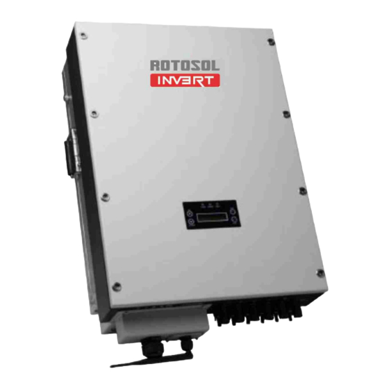
Page 8: Identifying The Inverter
3.2 Identifying the Inverter You can identify the inverter by the type label. Information such as serial number (Serial No.) and model name of the inverter, as well as the device's technical parameters are specified on the type label. The type label is on the right side of the enclosure. -
Page 9: Mounting
4 Mounting 4.1 Safety DANGER! Danger to life due to potential fire or electric shock. not install the inverter near any inflammable or explosive items. The inverter will be directly connected with high voltage power generation device. The installation must be performed by qualified personnel only in compliance with national or local standards and regulations. - Page 10 might lead to power reduction. Leave enough effective space around the inverter for better ventilation. • Vertical installation, wiring area must be downside, lateral installation is not allowed; in backward tilted installation, tilt angle should not exceed 30 degrees; Forward tilted, horizontal or inverted installation is not allowed.
-
Page 11: Mounting The Inverter With Wall Mounting Bracket
4.3 Mounting the Inverter with Wall Mounting Bracket Use the wall mounting bracket mark the drilling position and drill the holes for the screws. 2.Fix the wall mounting bracket with the equipped self-tapping screw. 3. Hang the inverter to the mounting bracket and ensure the slot is fitted on the bracket. 4. -
Page 12: Electrical Connection
Electrical Connection Notes: 1. Electrical installation & maintenance shall be conducted by licensed electrician and shall comply with local Wiring Rules. 2. After the inverter has been installed in its fixed position, the electrical connection to the unit can be established. -
Page 13: Overview Of The Connection Area
5.1 Overview of the Connection Area The following figures show the assignment of the individual connection areas on the bottom of theInverter. Object Description DC connectors ( + ) for connecting the PV strings DC connectors ( − ) for connecting the PV strings WiFi/RS485 Communication Waterproof Connector Waterproof Junction Box, AC connection DC Switch... - Page 14 Measure the grid voltage to make sure within the permissible range. Disconnect the circuit breaker between the inverter and the grid. Disconnect the DC and AC breaker, DC switch in the"OFF"state.. Disconnect the DC and AC breaker, DC switch in the"OFF"state. Assembly yellow-green Ground wire RV5.5-6 terminal, and connect to one ground terminal.
- Page 15 Prepare AC cable(Φ4mm2 or bigger), stripping length is 14±0.5mm. Connect the cable with terminals. Run the cable harness with the pressed terminals through the junction box and insert the black cable harness, L1, L2 and L3 into the caps of N, W, V and U as shown in the system connection diagram.
-
Page 16: Connection To The Pv Generator (Dc)
6. Close junction box and tight the screws 5.3 Connection to the PV Generator (DC) CAUTION! Unit Disconnection From Load Disconnect circuit breakers and switches on both AC and DC sides 5.3.1 Conditions for the DC Connection The connected PV modules must meet following requirements -Same type -Same model -Identical alignment... -
Page 17: Assembling The Dc Plug Connector
voltage will destroy the device): Type Maximum input voltage [Vd.c] Maximum input current [Ad.c] RIT5K 1000 11x2 RIT6K 1000 11x2 RIT8K 1000 11x2 RIT10K 1000 11x2 RIT15K 1000 22+11 RIT20K 1000 22x2 RIT30K 1000 33x2 RIT40K 1000 40x2 RIT50K 1000 36x3 RIT60K 1000... - Page 18 Assembly Instructions: ♦ Prepare the DC wire to connect the positive and negative DC arrays. Stripping length is 12~15mm, sectional area is 4 mm as below. ♦ Insert the DC wire to metal connecting tube. Make sure all line heads are in the connecting tube as picture blow.
- Page 19 fall off, see picture below. ♦ Insert the assembled cable into male/female connector. A "chick" sound can be heard when connecting correctly. Then tighten the cap. Refer to the picture below. 5.3.3 Connecting the PV Generator (DC) DANGER! Danger to life due to high voltage in the inverter. •...
- Page 20 Plug the DC plug connectors into DC terminals on Inverter. The inverter DC input is equipped with two groups(DC-A and DC-B) of connecting sockets for DC input , and each group contains two pairs of connecting sockets (DC+ and DC-). Make sure at least one pair of DC terminal in each group is connected with PV array in installation,and group A and B must be connected with two arrays separately but not with one array,see picture below.
-
Page 21: System Diagram
6 System Diagram The typical connection diagram for the entire PV system is shown in the following figure. 1. PV Panel: Provide DC power to inverter 2. Inverters: Converts DC (Direct Current) power from PV panel(s) to AC (Alternating Current) power. Because Inverter is grid-connected, it controls the current amplitude according to the PV Panel power supply. - Page 22 RIT10K RIT15K RIT20K RIT30K RIT40K RIT50K RIT60K LPS: Lightning protection system, refer to the fol owing options: AC side, nominal discharge current 20KA, second grade lightning protection, protection voltage 2.5KV DC side, nominal discharge current 20KA, second grade lightning protection, protection voltage 3.2KV 6.
-
Page 23: Operation
7 Operation Product Overview 7.1 Overview of Control and Displays There are four function keys on the front panel: UP, DOWN, ESC, ENT. The keypad is used for: Up and Down keys: Scrolling the displayed parameter, or modify the adjustable parameters; Esc and Ent keys: Cancel or Enter. -
Page 24: Commissioning
7.2 Commissioning After completing of the mechanical and electrical installation, the inverter could be put into operation. 1. Switch off DC and AC side circuit breakers and switches. 2. Wait until the screen is on and set up grid connection standard. (Please refer to 7.4.1 for specific operations) 3. -
Page 25: Lcd Display
Inverter will start up automatically with enough DC voltage provided by PV array. When starting up (POWER LED is on), it shows "Rotosol" on LCD in front of the inverter. The inverter will delay 1 second and automatically jump to the System Checking Interface. - Page 26 Press Ent to time setting interface. Press UP and DOWN to adjust number and press Ent. Set year, month, day, hour, minute and second one by one according to local time. 7.4.2 Main Interface When time setting is completed, press Ent to exit and system will enter into the main interface as below. The LCD will automatically enter into the main interface after system checking when the inverter starts up next time.
- Page 27 Etoday Total Generation Capacity today Etotal Total Generation Capacity ETPV1/ETPV2 Total Generation Capacity today in MPPT One/Two RunTim Total Running Time Today SumTim Total Running Time 7.4.3 Query Interface Press Ent on main interface to view related information in query interface. Eight choosing items on the query interface: System Info,Error Record,SET,Clear Record,Data &...
- Page 28 NG2Imp The insulation resistance of negative pole in PV2 Error Record In Error Record, it shows fault series number, the time fault happens, faulty code and error display. When fault happens, FAULT LED turns on. "Trouble Shooting" in Chapter 9 is for users to refer to investigate and solve the faults.
- Page 29 operated by after sales personnel to make sure the safety and normal operation of the inverter. Date & Time SET Press Ent to Date and Time setting interface.Press UP and DOWN to adjust number and press ESC go to next step. Set year,month,day,hour and minute one by one according to local time.
-
Page 30: Trouble Shooting
8 Trouble Shooting In most situations, the inverter requires very little service. However, if inverter is not able to work perfectly, we recommend the following solutions for quick troubleshooting. Error display Possble causes Corresponding measures EepromErr 1.Unstable PV Input voltage 1.After PV input voltage is stabilized, the machine will 2. - Page 31 Unbalanced current fault automatically restart. 2.Please contact with local dealer if error remains the same after several reset. IntFaultD 1.Electricity grid abnormal 1.After electricity grid returns to normal, machine will automatically restart. 2.Software over current fault 2.Please contact with local dealer if error remains the same after several reset.
- Page 32 IntProtectD l.PVside high current 1.Adjust the panel configuration to lower the input current. 2.Boost over current protection 2.Please contact with local dealer if error remains the same after several reset. IntProtectE 1.Electricity grid abnormal 1.After electricity grid returns to normal, the machine will automatically restart.
- Page 33 overcurrentprotection 2.Please contact with local dealer if error remains the same after several reset. IntProtectO MCU protection Please contact with local dealer if error remains the same after several reset. IntProtectP Frequency fault protection Reset grid frequency in accordance to local grid standard IntProtectQ DCI too high protection...
-
Page 34: Inverter Inspection And Repair
high 2. Remove foreign matter. 3. The heat sink or fan blocked 3.Please contact with local dealer if error remains the by foreign matter same after several reset. 4.Machinefailure TempSensorErr Abnormal temperature sensor Please contact with local dealer if error remains the same after several reset. -
Page 35: Repeat Countdown, Cannot Generation
c. check all of AC wiring connection point is well connected. 9.2.2 Isolation Fault Check PV array have leak current. 9.2.3 Input DC bus voltage High 9.2.3.1 check DC input voltage is within inverter’s input range; 9.2.3.2 check all of AC wiring connection point is well connected. 9.3 Repeat Countdown, cannot generation 9.3.1 check the resistance between PV(+) and ground, PV(-) and ground bigger than 2MΩ;... -
Page 36: Power Components Inspection(Without Dc Power Supply)
9.6.2 Generation difference between two or among three MPPT channels. a. check each MPPT channels’ input voltage not higher than 30%; b. check PV array’s tilt and azimuth angle is the same; c. check if the PV array have shading problem. 9.6.3( Grid line Voltage Fault) Fault Report a. - Page 37 Switch to the diode position of multimeter, please notice the ‘+’ and ‘-‘. The normal value is 0.33~0.37V(‘+’ with ‘-‘), ∞ (‘-‘ with ‘+’). And specific value could compare with normal inverter. Value close to the zero or bigger than normal range stands the diode is damaged. For the 5 generation models(total 4 measure positions)
- Page 39 9.7.2 IGBT / MOSFET a. IGBT b. MOSFET a. switch to the diode position of multimeter, and measure the value between Pin 3 and Pin 2, normal value is 0.3~0.4V. Value close to the zero stands the component is damaged; b.
- Page 40 9.7.3 Component Position Number Power Diode Position Number Generation Single MPPT Generation Dual-MPPT D9, D13, D30, D31 IGBT/MOSFET Position Number Generation Single MPPT Q2, QA1, QA2, QA3, QB1, QB2, QB3 Generation Dual-MPPT Q2, Q4, QA1, QA2, QA3, QB1, QB2, QB3...
-
Page 41: Mosfet Driver Inspection(For 5Th Generation Models)
9.8 MOSFET Driver Inspection(for 5th generation models) Remove the control board and control board mounting pad. Power the inverter with 100Vdc source and wait about 15 seconds. Measure the voltage of all of the MOSFET Pin 1 and Pin 3 separately, the normal driver voltage is -5Vdc. - Page 42 9.9.3 Select the SET menu by enter key and you will get the display as mention in Fig. 3 and Fig. 4. Fig.3 Fig.4 9.9.4 Press enter key to set the voltge range and enter the password as shown in Fig.5. Fig.
-
Page 43: Contact
Inverter SN Number Customer Information The contents of this manual are subject to change without further notice. For Rotosol latest product www.rotosol.solar information, please visit our website Rotosol Solar(Division of Solar – Rotomag motors and controls pvt ltd.) www. - Page 44 3.1 When a failure occurs, the user should check and record from the screen display the error code, DC voltage, AC voltage data or phenomena ect., then contact your local dealer. When the dealer or Rotosol confirm that it is the product quality problem ,the faulty product will be replaced.
- Page 45 4.Service Contact Customers could contact local dealer or distributor to discuss how to proceed. Please visit www.rotosol.solar for dealer/installer's contact details. Of course, customers may also contact Rotosol f they need help or advice. 5. Force Majeure Force majeure is not artificially unavoidable and insurmountable objective conditions.
- Page 46 Rotosol Solar(Division of Solar – Rotomag motors and controls pvt ltd.) www.rotosol.solar ADD: 2102/3 & 4 ,Vitthal Udhyognagar Near Anand, Gujarat – 388121 , India Phone : +91-9227110023/24/25 Customer Care Number : 1800-123-4412 E-MAIL: invert@rotosol.solar Website : www.rotosol.solar...
Need help?
Do you have a question about the RITxK Series and is the answer not in the manual?
Questions and answers