
Summary of Contents for BASENHURT Tebas EFka265
- Page 1 Tebas-Economic EFka265 INSTRUKCJA OBSŁUGI I INSTALACJI INSTALLATION AND MAINTENANCE INSTRUCTIONS...
- Page 2 OSTRZEŻENIA Niniejsza instrukcja przeznaczona jest dla personelu technicznego odpowiedzialnego za instalację, zarządzanie i utrzymanie urządzenia. Producent nie ponosi żadnej odpowiedzialności za uszkodzenia i usterki, które wystąpiły po interwencji przez osoby nieuprawnione lub przez zachowania niezgodne z instrukcją. Przed wykonaniem jakichkolwiek czynności konserwacyjnych i naprawczych, należy upewnić się, że system jest izolowany elektrycznie i hydraulicznie.
-
Page 3: Table Of Contents
Spis treści LISTA ELEMENTÓW ............................. 4 WSTĘP ................................4 INSTALACJA ..............................4 DANE TECHNICZNE ............................. 4 OPIS DZIAŁANIA SYSTEMU ........................5 PODŁĄCZENIE HYDRAULICZNE ......................... 6 Przewód ssący ..........................7 Przewód wtryskowy ........................7 PODŁĄCZENIE ELEKTRYCZNE ........................7 Kontrola poziomu ........................... 8 Kontrola przepływu ........................ -
Page 4: Lista Elementów
LISTA ELEMENTÓW Urządzenie Tebas-Economic EFka265 jest wewnętrznie podłączone i dostarczane z: 1. Elektrodą pH z 2.5 m kablem i złączem BNC 2. Elektrodą Redox z czujnikiem platynowym, 2.5 m kablem i złączem BNC 3. 2 uchwytami elektrod z zaciskiem DN50 do bezpośredniej instalacji elektrod 4. -
Page 5: Opis Działania Systemu
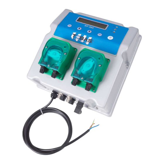
Wymiary OPIS DZIAŁANIA SYSTEMU Przedni widok • Panel sterowania z dużym wyświetlaczem i klawiaturą (patrz opis na następnej stronie) • Perystaltyczna pompka do dozowania kwasu • Perystaltyczna pompka do dozowania chloru Widok z dołu: podłączenia • POWER Kabel zasilający (uprzednio okablowany) •... -
Page 6: Podłączenie Hydrauliczne
Przedni panel dioda LED POWER zielone światło; wolne miganie oznacza, że urządzenie jest zasilane i pracuje normalnie podczas, gdy szybkie miganie uszkodzenie (brak środka do dozowania lub niesprawny magnes pompy) dioda LED OUT1, OUT2 czerwone światło podczas obracania się odpowiedniej pompki przycisk CAL zapewnia dostęp do „Konfiguracji”, „Kalibracji”... -
Page 7: Przewód Ssący
Przewód ssący (patrz rysunek) 1. Odkręć nakrętkę mocującą złącze znajdującą się na dole po lewej stronie głowicy pompy, oznaczonej na rysunku strzałką w górę. Odetnij przezroczysty wężyk PCW. 2. Włóż nakrętkę mocującą na wężyk. 3. Zamontuj rurkę na stożkowym uchwycie na złączu ssącym; przesuwając, aż do kołnierza stopującego. -
Page 8: Kontrola Poziomu
Kontrola poziomu (opcja) System jest już skonfigurowany do wyłączania dozowania w przypadku niskiego poziomu w zbiorniku. Kontrola poziomu odbywa się poprzez specjalny czujnik pływakowy (opcjonalnie, patrz „Dodatki i części zamienne”), który należy podłączyć do bolców 3 i 4 w złączu LEV (patrz rysunek). Gdy poziom środka chemicznego w zbiorniku spadnie poniżej czujnika poziomu, urządzenie zatrzyma dozowanie, a błąd pojawi się... -
Page 9: Podgląd Pomiarów
PODGLĄD POMIARÓW Podczas normalnej pracy, na wyświetlaczu w górnym rzędzie pojawią się dwie zmierzone wartości, dolny wyświetla stan dwóch pomp. W modelach Pt100 (opcjonalnie) dolny rząd przełącza się pomiędzy pomiarem temperatury a stanem dwóch pomp. Na przykład: “7.25pH 286mV” “P1 ON P2 020%” (pompa 1 ON w trybie ON/OFF, pump 2 ON w trybie proporcjonalnym ze wskazaniem procentowym) ⇓... -
Page 10: Lista Parametrów Konfiguracyjnych
Lista parametrów konfiguracyjnych W tym dziale wymienione są wszystkie parametry konfiguracyjne. Zaleca się, aby wypełnić ostatnią kolumnę ustawionymi wartościami ustalonymi dla danej opcji. Domyślna Ustawiona PAR. Opis Min. wartość Maks. wartość wartość wartość Działanie Pompy 1 ON-OFF / Proporcjonalny ON-OFF Wartość... - Page 11 PARAMETR 06 DZIAŁANIE POMPY 2 Ten parametr pozwala ustawić rodzaj funkcjonującej pompy 1, zwykle używanej do potencjału Redox. PARAMETR 07 WARTOŚĆ ZADANA POMPA 2 Patrz parametr P02, ale z odniesieniem do wartości Redox. PARAMETR 08 HISTEREZA POMPA 2 Patrz parametr P03, ale z odniesieniem do wartości Redox. PARAMETR 09 DOZOWANIE POMPA 2 Patrz parametr P04, ale z odniesieniem do Redox i opcjami „Chlorowanie/Odchlorowanie”.
-
Page 12: Kalibracja Elektrochemiczna
PARAMETER 19 RÓWNOWAGA pH Ten parametr pozwala określić maksymalny czas oczekiwania przed aktywacją regulacji Redox (chlor), podczas której tylko regulacja pH jest aktywna. Czas ten jest liczony od uruchomienia urządzenia, jednocześnie z możliwym opóźnieniem rozruchu ustawionym w P13, podczas którego cały system pomiarowy jest w trybie czuwania. Innymi słowy, regulacja pH jest aktywowana, gdy czas opóźnienia rozruchu (P13) upłynie, a regulacja Redox (chlor) jest aktywna, gdy pH osiągnie wartość... -
Page 13: Tryb Ręczny
Kalibracja Redox 1) Przepłucz elektrodę w wodzie destylowanej, a następnie zanurz w roztworze kalibracyjnym (np. 220 mV). 2) Naciśnij przycisk CAL, aby wejść do tryb menu i użyj przycisków ⇑ / ⇓, aby wybrać opcję “IN2 CALIBRATION” I N 2 C A L I B R A T . -
Page 14: Błędy/Alarmy
BŁĘDY/ALARMY Każdy błąd lub nieprawidłowość wykryta przez system generuje komunikat alarmowy na wyświetlaczu: LEV1 / LEV2 Czujnik poziomu 1 lub 2 wykrył niski poziom środka do dozowania; przywróć poziom w odpowiednim zbiorniku. FLOW Czujnik przepływu wykrył nieprawidłowość, która mogła wystąpić ze względu na niskie ciśnienie w obwodzie hydraulicznym lub niewłaściwą... -
Page 15: Dodatki I Części Zamienne
Przezimowanie pompki: Przed wyłączeniem systemu na przezimowanie, a także podczas dłuższego czasu nieużytkowania urządzenia, dozuj czystą wodę, aby przepłukać rurki, a następnie obróć w prawo uchwyt, aby ustawić go w sposób, jak pokazano na rysunku. Elektrody pH i Redox Zazwyczaj zalecane jest czyszczenie elektrod, gdy ich reakcja jest powolna, pomiary nie są wiarygodne albo gdy nie były używane przez dłuższy czas, w szczególności w agresywnych roztworach, zanieczyszczeniach, bardzo kwaśnych lub bardzo zasadowych warunkach. - Page 16 WARNINGS This manual is dedicated to the technical personnel responsible of the installation, management and maintenance of the plants. The manufacturer assumes no responsibility for damages or malfunctions occurring after intervention by non-authorized personnel, or not compliant with the prescribed instructions. Before performing any maintenance or repair action, ensure that the system is electrically and hydraulically insulated.
- Page 17 Table of content PACKING LIST .............................. 18 INTRODUCTION ............................18 INSTALLATION ............................. 18 TECHNICAL SPECIFICATIONS ........................18 FUNCTIONAL DESCRIPTION ........................19 HYDRAULIC CONNECTIONS ........................20 Suction Line ............................ 21 Injection Line ..........................21 ELECTRICAL CONNECTIONS ........................21 Level Control ........................... 22 Flow Control ............................
-
Page 18: Packing List
PACKING LIST The Tebas-Economic EFka265 unit is supplied already wired internally, and complete with: pH electrode with 2.5 m cable and BNC connector. Redox electrode with platinum sensor, 2.5 m cable and BNC connector. Two PVC electrode-holders with DN50 clamp for direct in-line installation of electrode. pH and redox calibration solutions, 90 ml bottles (pH4, pH7 and 220 mV). -
Page 19: Functional Description
Dimensions FUNCTIONAL DESCRIPTION OF THE SYSTEM Front view • Control panel with large display and keyboard (see description on next page) • Peristaltic pump for acid dosage • Peristaltic pump for chlorine dosage Bottom view: connections • POWER Power cable (pre-wired) •... -
Page 20: Hydraulic Connections
Front panel POWER LED Green light; slow flashing indicates that the unit is powered and normally functioning, while fast blinking indicates a fault (lack of liquid to be dosed or pump magnet disabled). OUT1, OUT2 LED Red light on during the rotation of the respective pump. CAL Key Provides access to the “Configuration”, “Calibration”... -
Page 21: Suction Line
Suction Line (also see drawing) 1. Unscrew the fixing nut of the connector located on the bottom left side of the pump head and marked in the figure with an incoming arrow. 2. Cut the transparent PVC Crystal tube. 3. Insert the fixing nut and the tube-wrench on the tube. 4. -
Page 22: Level Control
Level Control (optional) The system is supplied already configured for disabling the dosage in case of low level in the tank. The level control is made through a specific float sensor (optional, see “Accessories and spare parts”), to be connected to pins 3 and 4 of the LEV connector (see Figure). When the product level in the tank falls below the level sensor, the unit stops dosing and the fault is shown on the display. -
Page 23: Visualizations
VISUALIZATIONS During normal operations, the display shows the two measured values on the top line, while the bottom row displays the status of the two pumps. In models with Pt100 (optional) the bottom row switches between the temperature measurement and the status of the two pumps. For example: “7.25pH 286mV”... -
Page 24: Advanced Configuration
Advanced Configuration The advanced configuration mode also includes the parameters protected by password, that allow a complete configuration of the system. This mode is normally accessed only by authorized technical personnel. Once selected the “Advanced Configuration” option, press the A D V A N C E D C O N F I G . - Page 25 PARAMETER 03 HYSTERESIS PUMP 1 This parameter is sued to adjust the functioning hysteresis of pump 1 around the threshold set in P02. It is recommended to set a narrow window in case of ON-OFF mode, while for proportional mode it is advisable to set a window of at least points. PARAMETER 04 DOSAGE DIRECTION OF PUMP 1 This parameter allows to set the dosage direction.
-
Page 26: Electrochemical Calibration
PARAMETER 16 PASSWORD This parameter allows to enter a password (numeric value within 1 and 255) to protect the system from unauthorized access. Once set and confirmed, the password will be requested to access the menus “Advanced configuration” and “Manual mode”. The instrument is supplied with no password set (P16=0). -
Page 27: Manual Mode
Notes If the system does not automatically recognize the buffers or the “Calibration Impossible” error occurs, it can be due to: a) buffer solution contaminated or expired b) electrode faulty or dead c) connection cable or connector damaged If you try to calibrate the offset at a pH value too different from 7.00, the calibration is automatically ignored. Similarly if you try to calibrate the gain with a buffer solution at a pH too close to neutrality, the procedure will fail. -
Page 28: Errors/Alarms
Common settings for the two examples described above: - P13 start-up delay of 15 minutes (average time required for the polarization of redox electrodes) - P16 protection PASSWORD to prevent unauthorized access ERRORS / ALARMS Every error or anomaly detected by the system generates an alarm message on the display: LEV1 / LEV2 The level sensor 1 or 2 detected a low level of the liquid to be dosed;... -
Page 29: Accessories And Spare Parts
Pump wintering: Before shutting down the system for wintering or anyway for a long period, dose clean water to rinse the tube, then rotate the roller-holder clockwise to position it as shown in the figure. pH and Redox Electrodes Typically, it is recommended to clean the electrodes when the response is slow or measurements are not reliable, and when they have been used for a long time, especially in aggressive solutions, pollutants, very acidic or very alkaline environments.
Need help?
Do you have a question about the Tebas EFka265 and is the answer not in the manual?
Questions and answers
Hello I need the electric motor model (Meteor, Italy) 5R167DM001/01 for Efka dosing pump EF104/A-15-S or complete pump EF104/A-15-S. Please let me know the price and availability (lead time) Thank you