
Summary of Contents for F3A CONTRAST LT
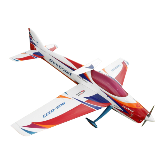
- Page 1 F3A CONTRAST LT INSTRUCTION MANUAL Wing Span - 1870 mm Lenght - 1980 mm Wing area - 60 dm Fly weight - 4850-4950 g...
- Page 2 European and the World Championships) and produced in Lithuania using top quality German made epoxy resin and glass/carbon fiber. This professional CONTRAST LT kit is the result of Sergey’s 25 years experience in F3A world and his research in best F3A performances.
-
Page 3: Table Of Contents
Table of Contents Warning 1. Available options 1.1. White Series 1.2. Painted in Molds Series 1.3. Custom Series 1.4. RTF Series 2. Kit Contents 3. Items Needed To Complete 3.1. Required Tools and Adhesiv 3.2. Power System Selection 3.3. Servos Selection 3.4. -
Page 4: Warning
! Warning ! 5. Model Assembly Process An RC aircraft is not a toy! If misused, it can cause serious bodily harm and damage to property. Fly only in open areas and AMA (Academy of Model Aeronautics) approved flying sites, following all instructions included with your plane, radio and engine, avoid flying near full-scale aircraft and avoid flying near or over groups of people. -
Page 5: Available Options
The all white CONTRAST LT is the most economical version of this high performance F3A plane. The all white CONTRAST LT is the most economical version of this high performance F3A plane. Kit includes: - Fuselage;... -
Page 6: Painted In Molds Series
The standard scheme with its elegant lines is just perfect for F3A, as it looks great in the air. We kept the style similar to other, typical F3A planes paint schemes, but we paid attention really well not to overload it with too much colors and shapes. - Page 7 Painted in Molds Series is highly prefabricated for you. Only few hours of work will be needed to get Contrast LT ready to fly. Kit includes: - Fuselage; - Preinstalled Chin Cowl; - Preinstalled Canopy; - Preinstalled Removable Rudder; - Preinstalled wings with hinged Ailerons and installed Aileron gap Covers;...
-
Page 8: Custom Series
1.3. Custom Series Custom Series is highly prefabricated for you. Only few hours of work will be needed to get Contrast LT ready to fly. All Custom Series planes will be airbrushed according to your wishes. The cowl, canopy, landing gear, wheel pants and tail wheel assembly are already installed. - Page 9 Kit includes: - Airbrushed and preinstalled Fuselage; - Airbrushed and preinstalled Chin Cowl; - Airbrushed and preinstalled Canopy; - Airbrushed and preinstalled Removable Rudder; - Airbrushed and preinstalled wings with hinged Ailerons and installed Aileron gap Covers;...
- Page 10 - Airbrushed and preinstalled Stabilizers with hinged Elevators and installed Elevator gap Covers; - Preinstalled Composite Landing gears; - Airbrushed Wheel pants; - Carbon fiber Wing tube, 25 mm Ø x 600 mm; - Hardware bag; - Custom made protection bag set (fuselage, wings, stabs); - CNC milled carbon fiber parts bag;...
-
Page 11: Rtf Series
RTF Series is fully assembled, trimmed and ready to flight planes. Only plug the batteries and your Contrast LT are ready to fly. Your Contrast LT, can and, will be provided with anything according to your own preferences: Only write to us what equipment you want and we will install it. -
Page 12: Kit Contents
2. Kit Contents Quantity Description Fuselage with hinged Removable Rudder; Preinstalled Chin Cowl; Preinstalled Canopy; Preinstalled Wing with hinged Aileron, right; Preinstalled Wing with hinged Aileron, left; Preinstalled Stab with hinged Elevator, right; Preinstalled Stab with hinged Elevator, left; Preinstalled Composite Landing gear, right; Preinstalled Composite Landing gear, left;... - Page 13 Hardware List Wing Pack (2 sets ) Pcs., Description 2 CNC milled carbon fiber or composit fiber aileron control horn; Ball Link M2; Carbon fiber Pushrod ( Steel) M2 x 150 mm; Bolts M2x15 Nuts M2; Threaded coupler M2; Stab Pack (2 sets) Pcs., Description CNC milled Darbon fiber...
-
Page 14: Items Needed To Complete
3. Items Needed To Complete 3.1. Required Tools and Adhesives Personal protective equipment The fuselage, dings, stabs, rudder, landing gears and other parts included in this kit are made of fiberglass and carbon fiber, the fibers of Chose may cause eye, skin and respiratory tract irritation. Never blow into a part to remove fiberglass and carbon fiber dust, as the dust will blow back into your eyes. - Page 15 Adhesives 15 and 30 Minute Epoxy Thick CA (cyanoacrylate) glue Masking Tape Double-Sided Tape Epoxy filler Thread Locker Acetone/Alcohol swabs or Rubbing alcohol; Paper or plastic caps Wooden coffee spoons Cotton buds Required Hardwares Main LiPo pack; Receiver LiPo pack; Receiver;...
-
Page 16: Power System Selection
Best efficiency and highest performance reached with (RTF weight 4900 grams): - AXI model motors 5330/F3A GOLD LINE brushless motor; - Jeti Advance 90 Pro Opto speed controller (or Castle Creations 110); - PT model 20 x 13 E” Carbon Propeller;... - Page 17 Lightweight setup: - Power Box System Digi-Switch (up to 12 A); - One (1) 2 S, 25C, H-Energy LiPo with capacity from 450 mAh to 600...
-
Page 18: Servos Selection
3.3. Servos Selection For the control surfaces of Contrast LT we recommend use follows Hitec servos: Ailerons – two (2) Digital Servos 5-6 kg/cm; Elevator – two Digital Servos 5-6 kg/cm or one (1) Digital High Speed Metal Gear Servo 8-9,5 kg/cm;... -
Page 19: Warranty Information
4. Warranty Information Before starting to build, inspect the parts to make sure they are of acceptable quality. If any parts are missing or are not of acceptable quality, or if you need assistance with assembly, please contact RC Composit. It is important to notify RC Composit of any damage or problems with the model within 30 days of receiving your airplane to be covered under warranty. -
Page 20: Model Assembly Process
5. Model Assembly Process 5.1. Wings Both wings are made in negative moulds, and fully vacuum bagged, using 2 layers of super light fiberglass in combination with a 2 mm Airex foam sandwich form a hard and durable outer skin. Each wing panel weighs between 310 and 325 grams, depending on the color scheme. -
Page 21: Aileron Control Horn Installation
5.1.1. Aileron control Horn Installation Use 15-30 minute epoxy to ensure adequate working and cleanup time... -
Page 29: Wing Servo Installation
5.1.2. Wing Servo Installation There are two options for mounting the servos: - inside the wing; - outside the wing; To achieve better aerodynamic quality and model look we recommend that you use the first option. -
Page 31: Elevator
5.2. Elevator The stabilizer parts are also vacuum bagged sandwich molded using lightweight fiberglass cloth and 1,5 mm Airex foam construction. The elevator control surfaces are elastic-hinged. Each elevator panel weighs between 90 and 100 grams, depending on the color scheme. From the bottom of the stabilizer, elevator gap are covered with glass fiber seal. -
Page 32: Elevator Control Horn Installation
5.2.1. Elevator control Horn Installation Use 15-30 minute epoxy to ensure adequate working and cleanup time. -
Page 37: Elevator Servo Installation
5.2.2. Elevator Servo Installation There are three options for mounting the elevator servos: - inside the elevator halves ( 2 servos) - on fuselage sides ( 1 servo) - Inside the fuselage with common elevator shaft and one servo. In order to reduce the weight of the model also to reduce the inertia of the tail and achieve best model flight characteristics we recommend that you use the last option. -
Page 41: Fuselage
5.3. Fuselage Fuselage are made in negative moulds, and fully vacuum bagged, using 2 layers of super light fiberglass in combination with a hard 2 mm Airex foam sandwich form a hard and durable outer skin. The complete front of the fuselage is reinforced with an additional layer of carbon cloth, from the LG supports forward to the nose-ring. -
Page 45: Canalizer Installation
5.3.2.1 Canalizer installation... -
Page 47: Tail Wheel Installation
5.3.2 Tail Wheel Installation There is a balsa plate already glued into the fuselage floor. -
Page 50: Landing Gear Installation
5.3.3. Landing Gear Installation The main landing gear legs are laminated from a number of carbon and glass rovings and cloth, in negative molds, and heat cured. This produces a strong, but still flexible and lightweight, structure. Each leg is secured through the underside of the fuselage, at the back of the chin cowl position, into the factory-installed carbon reinforced plywood mount. -
Page 55: Engine Mounting
(batteries, receiver, elevator servos etc) as far back as possible. Included in the kit is a carbon firewall for AXI model motors 5330/F3A, AXI 5325/24 and AXI 5325/18GOLD LINE brushless motors. -
Page 66: Battery Tray Installation
5.3.5. Battery Tray Installation... -
Page 74: Radio Equipment Installation
5.3.6. Radio Equipment Installation The plane can be ordered with two types of servo trays: - One servo version:... - Page 75 - Two servo version:...
-
Page 77: Balancing The Model/Control Throws
6. Balancing the Model/Control Throws At this stage the model should be in ready-to-fly condition with all of the systems in place including the brushless motor, servos, landing gear, the radio system, and battery packs. The recommended Center of Gravity location is 5-10 mm behind the wing tube Please use the battery pack, moving it forward or backward, to achieve the perfect balance. -
Page 78: Mixing The Model
Elevator Medium – 12.1° up, 15.5° down. 36% up and 46% down expo. I use this for takeoff, landing, and some downline snaps (where it is harder to show good break on entry of snap). Elevator Low – 10.4° up, 12.0° down. 23% up and 30% down expo. I use this for all normal flying, and most snaps. -
Page 79: Preflight
100% full left rudder – 9% down elevator 83% left rudder – 5% down elevator 60% left rudder – 4% down elevator 50% rudder (Center) – 0% 40% right rudder – 4% down elevator 17% right rudder – 5% down elevator 0% full right rudder –... - Page 80 Step. 3 Check trims and sub trims are set to neutral and controls centered. Check rate and flight mode switches set properly. If you are using MHz radio check the receiver antenna is fully extended and not reversed on it self. Always double check to make sure your transmitter antenna is fully extended.
Need help?
Do you have a question about the CONTRAST LT and is the answer not in the manual?
Questions and answers