
Related Manuals for SnowDogg VUT Series


Summary of Contents for SnowDogg VUT Series
- Page 1 9049 Tyler Blvd. • Mentor, Ohio 44060 Fax (440) 974-0165 • Toll-Free Fax 800-841-8003 snowdoggplows.com 16992440 Rev A...
-
Page 2: Table Of Contents
For recommended vehicle models and the front and rear weight distribution ratio. refer to the SnowDogg Application Chart and In some cases, rear ballast may be required to Selection Guide. comply with these requirements. -
Page 3: About The Plow
WELCOME! Congratulations on your purchase of a SnowDogg plow! The SnowDogg plow by Buyers Products is a heavy- duty, professional grade plow built for your toughest plowing applications. By using this manual for maintenance and safety instructions, you can be sure to optimize the life of your plow. -
Page 4: Snowplow Mounting/Dismounting
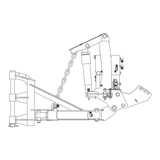
MOUNTED PLOW DISMOUNTED PLOW MOUNT/DISMOUNT INSTRUCTIONS Snowplow Mounting (fig. above) Snowplow Dismount (fig. above) 1. Check that the pins are fully retracted. The foot 1. Put the plow in float by holding the down button for pedal should be pushed towards the truck and will 1 second. - Page 5 INSTALLATION SnowDogg snowplows are shipped almost completely assembled to minimize the amount of time from box to plowing. The illustrations are representative only and may differ from your hardware. Please see the parts diagrams for specific part numbers. ITEM QTY.
-
Page 6: Mechanical Installation
SNOWPLOW ASSEMBLY Attach the chain lift to the upper lift frame and lift cylinder using two 7/8" x 4" clevis pins and cotter pins (10a/b). Attach the moldboards to the lift frame kit using the hinge pin, washer, and cotter pin as shown. Check that the moldboards rotate freely around the hinge pin. - Page 7 Control Harness Diagram 10A FUSE TRUCK FIREWALL DRILL Ø1.5" HOLE AND TO CONTROLLER PROTECT WITH GROMMET POSITIVE (+) TERMINAL NOT USED TO CHASSIS OR BATTERY GROUND NEGATIVE (-) TERMINAL THROUGH GRILL 16160300 CONTROL HARNESS CONTROL HARNESS (continued) 5. The large (4 gage) BLACK WIRE on the CONTROL HARNESS must be connected directly to the NEGATIVE (-) battery terminal.
-
Page 8: Storage And Maintenance
4. Connect plow to vehicle MAINTENANCE The SnowDogg line of plows has been simply designed for reliable service. In order to ensure the reliability of your plow, observe the following maintenance items and regularly inspect: • Fasteners and retaining devices for proper installation and tightness. -
Page 9: Parts Diagram And Bom
Figure A - Lift Frame Diagram Figure B - Linkage Detail Diagram Figure C - A-Frame Diagram 16992440 Rev A... -
Page 10: Moldboard
Moldboard Diagram VUT Harness 16992440 Rev A... -
Page 11: Hydraulic Power Unit
Hydraulic Power Unit Diagram Hydraulic Power Unit Wiring Diagram GRN/WHT ORG/WHT RESERVOIR SIDE MOTOR SIDE BLUE ORANGE BLU/WHT MOTOR GREEN BLU/WHT PURPLE ALL COILS GROUNDED TO NEGATIVE MOTOR TERMINAL BLUE 16992440 Rev A... - Page 12 9049 Tyler Blvd. • Mentor, Ohio 44060 Phone (440) 974-8888 • Fax (440) 974-0165 Toll-Free Fax 800-841-8003 • snowdoggplows.com Parts List Qty DESC Qty DESC 16101180 Hinge Pin Kit 16152018 Plug, -4 SAE 16101202 Spring, Torsion Trip, DS 16151325 Connector, -4 SAEM/JICM 16101203 Spring, Torsion Trip, PS 16153100...
-
Page 13: Hydraulic/Electrical Operation
DRIVER SIDE PASSENGER SIDE BORE BORE TO RESERVOIR TO RESERVOIR TOP BLOCK CENTER BLOCK PUMP/RESERVOIR LOGIC TABLE DOWN FLOAT LEFTIN NOTE LEFTOUT Full schematics and pin out RIGHTIN RIGHTOUT information can be found online at www.snowdoggplows.com under SCOOP Tech Support in the 16992920 ANGLEFT service manual. -
Page 14: Troubleshooting
TROUBLESHOOTING Disconnect the RELAY MODULE CONNECTOR for the following steps. The controller will not detect most electrical faults with the relay module connected. Symptom/Diagnostic Result PUMP MOTOR NOT RUNNING WHEN UP, LEFT OR RIGHT PRESSED Status light blinks ONCE Continuity Problem Check RED WIRE/MOTOR RELAY Check voltage at MOTOR terminals with UP, If voltage present - MOTOR is bad... - Page 15 TROUBLESHOOTING (continued) Symptom/Diagnostic Result Check S1A VALVE for contamination Poppet must move freely, and seat area Remove S1A VALVE and check free movement of must be clear of any debris poppet, clean any chips/debris from valve Replace S1A VALVE LEFT OR RIGHT WING WON'T EXTEND Status light blinks 5 times Continuity Problem Check BLUE/WHT WIRE/S4 and S5 COILS...
-
Page 16: Snow Plowing Tips
Buyers Products. To obtain service, the purchaser must return the defective snowplow to an authorized SnowDogg Dealer with proof of purchase and applicable maintenance records. All transportation costs to and from the dealer will be the responsibility of the purchaser. SnowDogg dealers may be located on-line at www.snowdoggplows.com.
Need help?
Do you have a question about the VUT Series and is the answer not in the manual?
Questions and answers