
Summary of Contents for CamMate Roomer
- Page 1 ® CamMate Operations Manual CamMate Systems Phone: (480) 813-9500 Fax: (480) 813-9292 425 E. Comstock Chandler, AZ 85225 USA www.cammate.com cammate@cammate.com...
- Page 2 ATTENTION Verify clean AC power (100-240vac) before connecting CamMate Electronics Control Box. A surge suppressor or line conditioning device is recommended when connecting this unit to AC power. The power supply in this unit auto-senses line input voltage but incorrect input voltages or incorrect wiring of the AC power source may result in damage to the unit and void the warranty.
-
Page 3: Table Of Contents
Table of Contents § CamMate Systems Assembly Guide, Introduction Safety Precautions § § Pedestal/Leveling/Main Boom Section § Tilt Brake Knob, Tail Section § Boom Securing Brake, Drag § Control Rod Installation § Adjustable Monitor Bracket Head Mounting § § CamMate Electronics Assembly § ... -
Page 4: Cammate Systems Assembly Guide, Introduction
Due to weight and leverage considerations fluid heads will not maintain the system in a safe operating environment. No matter how tight you secure it, failure will occur. If you are not using a CamMate dolly or tripod for mounting your system and are not sure of the mount you intend to use, please consult CamMate. -
Page 5: Safety Precautions
9. Never swing or position the boom in a manner that would risk contact with people or objects. Know your boundaries before you begin shooting. If you have questions after reading this manual, please call CamMate. For technical 10. Be aware that understanding the disassembly of the boom is just as questions please contact our CamMate trained technicians. -
Page 6: Pedestal/Leveling/Main Boom Section
Turn the Turnbuckles accordingly until leveling is achieved. (See page 53 for Dolly assembly.) Note: Only hand tighten Turnbuckles. Tighten them inwards, drawing the Dolly Tube and Dolly Base towards each other. Level Here Dolly Tube Turnbuckle Pictured: Roomer Dolly... - Page 7 Pedestal Set the Pedestal onto the Dolly Tube or Riser mount. Using the Pedestal Mounting Knob, securely attach the Pedestal to the top of the Dolly Tube. If a Riser is used, attach the Pedestal on top of the Riser (shown on page 47). Note: The keyway of the Pedestal must be in the slot.
-
Page 8: Tilt Brake Knob, Tail Section
Tilt Brake Knob Insert the Tilt Brake Knob through the Pedestal. Slide the Brake Washer between the Tilt Brake and Pedestal, then slide the knob through the Tilt Brake. Finally, install the Tilt Brake Nut. Tilt Brake Brake Tilt Brake Washer Tail Section Knob... - Page 9 Tail Section Continued… T-Bolt Slot T-Bolt Edges flush when tight Tail Section Main Boom Section or Tail Connecting Tongue Extension Section While lowering the T-Bolt from the Tail Section into the T-Bolt Slot on top of the Main or other section, slide the Connecting Tongue from the adjoining Tail or other extension section toward the Main Section, aligning screw holes.
- Page 10 Tail Section Continued… Note : This page only applies to 2000 Series Cranes. 1. Place the end of the Turnbuckle that has the R mark, toward the Tail Section. (This will allow all of the Turnbuckles to tighten and loosen in the same direction.) 2. ...
-
Page 11: Boom Securing Brake, Drag
Boom Securing Brake, Drag The tilt and pan brakes for the boom are controlled by the Tilt Brake Knob and Tee Bar, located on the same side of the Pedestal. The Tilt Brake Knob controls braking for boom tilt and can be used to add drag as needed. -
Page 12: Control Rod Installation
Control Rod Installation Note: Install the Control Rod while installing each boom extension section. 1. Screw the Pedestal Control Rod into the Pedestal Control Rod Connector. (See image on page 6). 2. Slide the Control Rod through the Control Rod Clamp. Then screw the Control Rod into the Pedestal Control Rod. -
Page 13: Adjustable Monitor Bracket
Adjustable Monitor Bracket The Adjustable Monitor Bracket mounts on top of the Control Box, by inserting the ¼” Quick Release Pin through the Hanger Bracket and Hanger Bracket Block, attached to the Control Box . Next, secure the Hanger Bracket to the Tail Section by using the Hanger Bracket Knob. -
Page 14: Head Mounting
Mounting the Head The Head Mount Bracket (Fork) is attached to the L-Head from the factory. (See page 17 for Upright Head mounting instructions.) Install the Head Mount Bracket to the Nose Assembly by using the supplied (4) 1/4”-20 Knobs. Head Mount Bracket Nose Assembly Place a torpedo level on... -
Page 15: Cammate Electronics Assembly
CamMate Electronics Assembly 1. Mount the Control Box to the Tail Section of the boom, using the Hanger Bracket Knob, as shown on page 12.) 2. Run the Main Cable down the length of the boom, securing with Bungie Straps. -
Page 16: Lens Control Assembly
8. Connect the 8-Pin Connector from the Lens Cable to the lens. Servo Bracket 9. Some Fujinon lenses use a 12-pin connector. Use the 8-pin to 12-pin Focus Servo adaptor (ECF-126), supplied with your CamMate System. Iris Servo/ Gear Servo... -
Page 17: Lens Control Assembly
Lens Control Assembly Continued… Lens Control Cable Iris Mini XLR 8-Pin Connecto Servo Assembly 14 Pin Focus Mini XLR Lens Connector Head Connections 8 Pin Multi Connector Lens Selector 14 Pin Panel Connector... -
Page 18: Upright Head Operations
Upright Head The Head Mount Bracket (Fork) is attached to the L-Head from the factory in the Down Position. If your shot requires a higher viewpoint, you can mount the head in the Upright Position. 1. Simply remove the Head Mount Bracket (Fork) from the Nose Assembly by removing the 4 Mounting Knobs. -
Page 19: Dis-Assembly/Repacking
Dis-Assembly and Repack Tear down of the boom should be exactly reverse of the setup. Always rest the camera end of the boom onto a solid surface, like a C-Stand, or have a helper hold up the end when dis-assembling the boom. Then start unloading the weights from the Operator end of the boom. -
Page 20: Travel Series Cable Assist
Travel Series Cable Assist Setup Cable Assist Kits are standard for Travel 25’ and CamVoyager 29’. CamMate can provide Cable Assist Kits for shorter booms. 1. Insert the 3 Cable Support Rods into the Main Section’s Rod Holes (two on sides and one on top). - Page 21 Cable Support Rods Overhead Cable Ratchet Strap Assembly Tail Extension Section Tail Section Side Cable Rod Holes Main Section Slot Block Nose Assembly Last Extension Section...
-
Page 22: 2000 Series Cable Assist
2000 Series Cable Assist Setup Cable Assist Kits are standard for 2032, 2039, 2043 and 2050. CamMate can provide Cable Assist Kits for shorter booms. Note: Cable lengths are color coded for easier identification. 2032 Series Crane Cable Assist Setup - Side Cables only. - Page 23 2043 Series Crane Cable Assist Setup - 2043 & 2050 Systems both come with three 48” Steel Cable Support Rods & three 30” Aluminum Cable Assist Support Rods. The 48” rods are used with 2043 & 2050 Systems. The 30” rods are used with 2032 &...
- Page 24 2050 Series Crane Cable Assist Setup - Follow all seven 2043 Cable installation instructions on page 22. 8. Next, add the last 2 YELLOW cables to the GREEN cables at the back of the crane. When the Side Cables are tight, install the 24” & 20” Cable Support Rods in the Side Rod mounting bracket located on 2 &...
-
Page 25: Camera Leveling/Balancing
Camera Leveling There are two handles on the Camera Table. (See picture on page 25.) If you put your camera on the Camera Table and it tilts the table downward, which will cause your picture to be unleveled, a twist of the Table Tilt Adjustment Handle will change the angle of the table to compensate for your camera’s weight. - Page 26 Table Height Adjustment Knob Camera Cradle Assembly Table Lock Handle Table Tilt Adjustment Handle Cradle Lock Handle Camera Plate Camera Table Camera Knob...
-
Page 27: Engaging Motors
Engaging Motors Note: Only engage the motors after camera is balanced. Tilt Motor 1. Loosen the two Motor Knobs , then slide the Tilt Motor until the gears mesh, and then tighten the Motor Knobs. Note: Always disengage the Tilt Motor before removing camera. -
Page 28: Operator Notes
Operator Notes... -
Page 29: Controls Manual
CamMate ® Controls Manual... -
Page 30: Table Of Specifications
Table of Specifications Dimensions 10.75” W x 10.75” D x 4.75”H Weight Approximately 15 Lbs. AC Power Input 100/240VAC @ 1.0-1.5 Amps Camera Power Supply 15.25V @ 10 Amps Pan Speed 6000 RPM Motor. Approximately 4.8 seconds in 1 revolution. Tilt Speed 6000 RPM Motor 180°... -
Page 31: Joystick Controls
Joystick Controls Pan and Tilt Control Left to right movement of the Joystick proportionally controls Pan direction and speed of the Head. Joystick The first Personality Switch changes the direction of the Joystick’s Pan control. Forward and back movement of the Joystick proportionally controls the Tilt direction and speed of the Head. - Page 32 Joystick Controls Continued… Zoom Enable Press the Zoom Push Button to enable/disable zoom function. Start/Stop Switch Toggle the switch to start and stop camera’s recording function. Start/Stop Switch Zoom Push Button...
-
Page 33: Pistol Grip Controls
Pistol Grip Controls Focus Control Clockwise and counter-clockwise turning of the Focus Knob proportionally controls Focus direction and speed. The Focus Personality Switch changes the direction of the Focus control. Zoom Control Focus Personality Switch Pressing the Zoom Rocker controls Zoom Width and Tightness. Zoom Rocker Iris Knob Focus Knob... -
Page 34: Control Box Front Panel
Control Box Front Panel 1) Pan direction LED’s. 2) Tilt direction LED’s. 3) Zoom direction LED’s. 4) Zoom Enable indicator LED. 5) Pan Controls: Speed: This varies the Pan Motor’s top speed over a 5:1 range. Center: This controls the centering of the Pan Motor. Damp: This control will vary the amount of dampening applied to the Pan Motor. -
Page 35: Control Box Back Panel
Control Box Back Panel 1) 16-Pin CPC input connector from Joystick. 2) 37-Pin CPC connector, connects Main Cable to Head. 3) DC System Fuse (10 amp 125v Fast-Blow) 4) AC Line Fuse (3 Amp/125v Slow-Blow) 5) AC Line input connector. 6) ... -
Page 36: Operator Notes
Operator Notes... -
Page 37: Crab Dolly Manual
CamMate ® Crab Dolly... -
Page 38: Table Of Specifications
Table of Specifications The CamMate Crab Dolly utilizes all-wheel-steering. Crab Dolly without Support Pack Travel 25’ and all shorter cranes Assembled height 48 5/8” with 36” Tube. 60 5/8” with 48” Tube. Weight 103 Lbs. with 36” Tube. 108 Lbs. with 48” Tube. -
Page 39: Crab Dolly Assembly Guide
Crab Dolly Assembly Guide The best application for our CamMate Crab Dolly is a studio floor, but it can also be used on other hard surfaces such as dirt roads, parking lots, etc. Place the Dolly Tube over the Mounting Plate. -
Page 40: Crab Dolly Support Pack
Crab Dolly Support Pack The Dolly Support Pack was designed to provide more stabilization, especially for longer length cranes. The Dolly Support Pack should be installed before crane assembly. Crab Dolly Support Pack Note: It is recommended that the support pack be installed before the boom assembly. -
Page 41: Crab Dolly Support Pack
Crab Dolly Support Pack Continued… Slide the Dolly Support Legs into the Remove the three bolts that hold on the Bottom Plate (image on page Dolly Support Pack openings, align the holes in the Legs with the holes in 38). After the Bottom Plate is removed, the Dolly Support Pack the Dolly Support Pack and install the Locking Pins. -
Page 42: Operator Notes
Operator Notes... -
Page 43: Tripod With Wheels Manual
CamMate ® Tripod with Wheels... -
Page 44: Table Of Specifications
Table of Specifications Tripod with Wheels Travel 25’, 2024 and smaller cranes ONLY Assembled height 53 3/4” with 6” Riser 59 3/4” with 12” Riser Weight 80 Lbs. with 6” Rise 83 Lbs. with 12” Riser Footprint 40.5” X 48.5” CAUTION When repositioning the dolly, always push from the bottom of the dolly with someone at both ends. -
Page 45: Tripod Assembly Guide, Tripod With Wheels Leveling
Tripod Assembly Guide Install the Rear Legs first (see page Tripod with 45). Slide leg into the Tripod with Wheels Center Plate. Align holes in Wheels Center Plate with corresponding Leg Top View Center Plate Holes 1 & 2. Press the Quick Release Pin into Hole 1. - Page 46 Tripod Assembly Guide Continued… Installed Legs Wheels Assembly Steering Leg Tripod Mounting Right Rear Leg Hole Left Rear Leg Note: Pictured with Studio Wheels (Pneumatic Tires are also available).
- Page 47 Tripod Assembly Guide Continued… The Tripod Assembly is shipped in the folded position. To unfold, loosen the Center Post Lock (image on page 47) and pull legs outward. The Tripod Feet are shipped 180° out of operational orientation. Loosen the Tripod Leg Locks and rotate Tripod Feet 180°.
- Page 48 Tripod on Wheels Leveling Note: After the Tripod is mounted to the Wheels Assembly (see mounting instructions on previous page) and before the Pedestal can be mounted onto the Riser, the Tripod must be level. Tighten the Center Post by turning the Center Post Handle clockwise into the Riser.
- Page 49 Tripod Assembly Guide Continued… Note: The Steering Handle can be installed at anytime, using the Quick Release Pin to attach it to the Steering Handle Mount. After the Tripod is level, adjust Screw Jacks to the floor. Steering Handle Quick Release Pin Screw Jack Steering...
-
Page 50: Operator Notes
Operator Notes... -
Page 51: Roomer/Roamer Dolly Manual
® CamMate Roomer/Roamer Dolly Manual... -
Page 52: Table Of Specifications
33” X 69” without Outriggers 60” X 69” with Outriggers Roamer Dolly Required Dolly for 2039, 2043 & 2050 (Can be used with all CamMate Booms) Assembled Height 45” with 36” Dolly Tube 57” with 48” Dolly Tube Assembled Weight 266 Lbs. -
Page 53: Roomer/Roamer Assembly Guide
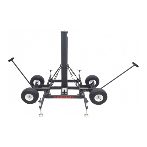
Roomer/Roamer Assembly Guide Note: Always place a sand bag behind the wheels when on an incline, to keep the dolly from rolling. Dolly Tube Mounting Knob Safety Push/Pull Outrigger Strap Steering Mounting Handle Perch Eyebolt Handle Plate Mounting Mount Knob... -
Page 54: Roomer/Roamer Assembly Guide
Roomer/Roamer Assembly Guide Continued… Place the Dolly Tube over the Mounting Plate. Tighten the Dolly Tube Mounting Knob, and install the four Turnbuckles. Place the end of the Turnbuckle that has the 5/8 mark toward the Dolly Tube Eyelet. This will allow all of the Turnbuckles to be tightened and loosened in the same direction. -
Page 55: Outrigger/Steering Handle & Push/Pull Handle Assembly
Roomer/Roamer Assembly Guide Continued… Outrigger/Steering Handle & Push/Pull Handle Assembly 1. Remove the Outrigger’s Quick Release Pin and Mounting Knob from Dolly Base. 2. Slide Outrigger into position and insert Quick Release Pin. Secure Outrigger with Mounting Knob. 3. Repeat Steps #1 and #2 for the remaining Outriggers.
Need help?
Do you have a question about the Roomer and is the answer not in the manual?
Questions and answers