Advertisement
Available languages
Available languages
Quick Links
Approvals
Hazardous Locations
Class I, Div. 2, Groups A, B, C, D
Class II, Div. 2, Groups E, F, G
Class III
CLI, ZN1, AEx em II T*
Ex em ll T*
BR-Ex em II
E-100-L is IECEx certified for use with:
BTV-CR/BTV-CT:
QTVR-CT:
XTV-CT:
KTV-CT:
VPL-CT:
(1)
Except VPL
*For system Temperature Code, see heating cable or design documentation
Kit Contents
Item Qty
Description
A
1
End seal and light assembly
B
2
Insulated parallel crimps (blue)
C
1
End seal label
D
1
Cable lubricant
E
1
Cable tie
F
1
Core sealer
WARNING:
This component is an electrical device that must be
installed correctly to ensure proper operation and to
prevent shock or fire. Read these important warnings
and carefully follow all of the installation instructions.
• To minimize the danger of fire from sustained
electrical arcing if the heating cable is damaged
or improperly installed, and to comply with the
r equirements of Tyco Thermal Controls, agency
certifications, and national electrical codes, ground-
fault e quipment protection must be used. Arcing may
not be stopped by conventional circuit breakers.
• Component approvals and performance are based
on the use of Tyco Thermal Controls-specified
parts only. Do not use substitute parts or vinyl
electrical tape.
(1)
IECEx BAS 06.0043X
IECEx BAS 06.0045X
IECEx BAS 06.0044X
IECEx BAS 06.0046X
IECEx BAS 06.0048X
.
• The black heating cable core and fibers are
conductive and can short. They must be properly
insulated and kept dry.
• Damaged bus wires can overheat or short. Do not
break bus wire strands when scoring the jacket or
core.
• Keep components and heating cable ends dry
before and during installation.
• Bus wires will short if they contact each other.
Keep bus wires separated.
• Use only fire-resistant insulation materials, such
as fiberglass wrap or flame-retardant foam.
• Leave these installation instructions with the user
for future use.
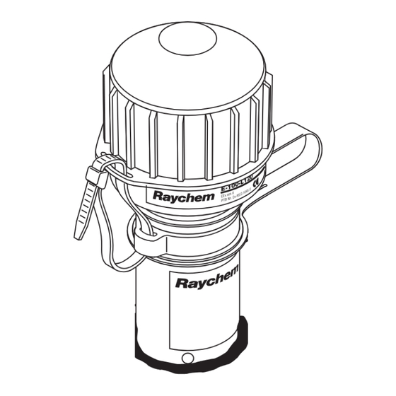
E-100-L
High-Profile End Seal with Light
Installation Instructions
Description
The E-100-L is a NEMA 4X-rated end seal kit with a light that indicates
voltage at the end of the circuit. It is designed for use with Raychem
BTV-CR, BTV-CT, QTVR-CT, XTV-CT, KTV-CT, and VPL-CT industrial
parallel heating cables. Once installed, the end seal is easily re-entered for
maintenance and the heating cable can be accessed without removing the
end seal. The LED indicator light provides excellent visibility.
This kit may be installed at temperatures as low as –40°F (–40°C). For
easier installation store above freezing until just before installation.
Two units are available:
E-100-L1 for 100–120 volts.
E-100-L2 for 200–277 volts.
Make sure voltage rating of light is the same as that of the heat-tracing circuit.
For technical support call Tyco Thermal Controls at (800) 545-6258.
Tools Required
• Wire cutters
• Needle nose pliers
• Panduit CT-100 crimp tool or equivalent
Additional Materials Required
• Pipe strap
Optional Materials
• Small pipe adapter for 1 in (25 mm) and smaller pipes:
Catalog number JBS-SPA P/N E90515-000
Leash
Strain
relief
A
Stand
F
CAUTION:
Health Hazard: Prolonged or repeated contact
with the sealant in the core sealer may cause skin
i rritation. Wash hands thoroughly. Overheating or
burning the sealant will produce fumes that may
cause polymer fume fever. Avoid contamination of
cigarettes or tobacco. Consult MSDS VEN0033 for
further information.
CHEMTREC 24-hour emergency telephone:
(800) 424-9300.
Non-emergency health and safety information:
(800) 545-6258.
®
• Utility knife
• Slotted screwdriver or nutdriver
• GT-66 or GS-54 glass cloth tape
B
Light
C
D
E
Advertisement

Subscribe to Our Youtube Channel
Related Manuals for Raychem E-100-L1

Summary of Contents for Raychem E-100-L1
- Page 1 Installation Instructions Description The E-100-L is a NEMA 4X-rated end seal kit with a light that indicates voltage at the end of the circuit. It is designed for use with Raychem ® BTV-CR, BTV-CT, QTVR-CT, XTV-CT, KTV-CT, and VPL-CT industrial parallel heating cables.
- Page 2 E-100-L Installation Instructions Heating Cable Types Outer jacket Braid Outer Outer jacket Braid Inner jacket jacket Braid Heating element Inner jacket Inner jacket Bus wire connection Conductive fiber Clear jacket Conductive core Spacer Insulated bus wire Bus wire Bus wire VPL-CT BTV-CR, BTV-CT, QTVR-CT XTV-CT, KTV-CT...
- Page 3 E-100-L Installation Instructions XTV, KTV BTV, QTVR Do not cut bus wires Do not cut bus wires • Measure exactly • Measure exactly 1 3/8 in (35 mm). 1 3/8 in (35 mm). 1 3/8" 1 3/8" • Lightly score (35 mm) (35 mm) • Lightly score inner jacket inner jacket around and down around and down as shown.
- Page 4 E-100-L Installation Instructions Do not cut bus wires • Measure exactly 1 3/8 in (35 mm). • Lightly score inner 1 3/8" jacket around and (35 mm) down as shown. • Peel off inner jacket. • Unwind heating element, cut and remove as shown. • Lightly score clear jacket around and down as shown. • Remove insulation from ends of bus wires.
- Page 5 E-100-L Installation Instructions • Mark the jacket CAUTION: Health Hazard. as shown. Wash hands after contact with sealant. Consult material safety data sheet VEN0033. • If needed, re-twist and straighten bus wires, then insert bus wires into guide tubes as shown. Make sure all strands Tubes go into the tubes. 5/8"...
- Page 6 E-100-L Installation Instructions • Fasten end seal stand to pipe with pipe strap. Note: For 1 in (25-mm) Do not pinch heating cable. Be sure pipe strap and smaller pipes use is under heating cable. adapter (purchased • Loop and tape extra heating cable to pipe. separately) between Minimum bend radius is 3/4 in (20 mm). stand and pipe. JBS-SPA adapter for small pipes Position adapter this...
- Page 7 E-100-L Installation Instructions • Insert cable tie through the slot on stand and the slot on the light, then tighten. • Apply insulation and weather-seal the stand entry. • Fasten end seal label to insulation. • Leave these instructions with the end user for future reference. Trim Weather seal...
-
Page 8: Troubleshooting Guide
4. With circuit off, attach volt meter leads to crimps. Energize circuit and measure voltage at light. Use the following table to determine whether the voltage measured is within the acceptable range. Catalog name Nominal voltage Acceptable voltage range E-100-L1 100–120 Vac 58–132 Vac E-100-L2 200–277 Vac 145–305 Vac • If voltage at light is in acceptable range and connections are good, the light may be defective or damaged. -
Page 9: Instruções De Instalação
É projetado para uso com os cabos paralelos de aquecimento industrial modelos BTV-CR, BTV-CT, QTVR-CT, XTV-CT, ® KTV-CT e VPL-CT da Raychem . Uma vez instalado, o terminal final é facilmente reintroduzido para manutenção e o cabo aquecedor pode ser acessado sem retirar o terminal final. - Page 10 Instruções de instalação do E-100-L Tipos de cabo aquecedor Capa externa Blindagem Capa externa Capa externa Blindagem Capa interna Blindagem Elemento de aquecimento Capa interna Capa interna Conexão do fio condutor Fibra condutiva Capa transparente Núcleo condutivo Espaçador Fio condutor isolado Fio condutor Fio condutor VPL-CT...
- Page 11 Instruções de instalação do E-100-L XTV, KTV BTV, QTVR Não corte os fios condutores Não corte os fios condutores • Meça exatamente • Meça exatamente 35 mm (1 3/8 pol.). 35 mm (1 3/8 pol.). 1 3/8 pol. 1 3/8 pol. • Corte ligeiramente • Corte ligeiramente (35 mm) (35 mm) ao redor da ao redor da capa interna e capa interna e...
- Page 12 Instruções de instalação do E-100-L Não corte os fios condutores • Meça exatamente 35 mm (1 3/8 pol.). • Corte ligeiramente ao redor da capa interna e 1 3/8 pol. (35 mm) longitudinalmente como mostrado. • Retire a capa interna. • Desenrole o elemento de aquecimento, corte e retire como mostrado. • Corte ligeiramente ao redor da capa e longitudinalmente como mostrado.
- Page 13 Instruções de instalação do E-100-L • Marque a capa CUIDADO: Risco para a saúde. como mostrado. Lave as mãos depois de entrar em contato com o vedante. Consulte a Ficha de Informações de Segurança de Produto Químico (FISPQ) VEN0033. • Se necessário, endireite e torça novamente os fios condutores e, em seguida, introduza os fios condutores nos tubos de guia como mostrado.
- Page 14 Instruções de instalação do E-100-L • Fixe o terminal final no tubo com a abraçadeira para Nota: Para tubos de 25 tubo. Não aperte o cabo aquecedor. Certifique-se de mm (1 pol.) ou menores, que a abraçadeira para tubo fique debaixo do cabo use o adaptador (adquirido aquecedor. separadamente) entre • Faça um laço e fixe o cabo aquecedor no tubo com o suporte e o tubo.
- Page 15 Instruções de instalação do E-100-L • Introduza a abraçadeira através da ranhura no suporte e da ranhura no módulo da lâmpada e, em seguida, aperte-a. • Aplique isolamento e vedação hermética na entrada do suporte. • Fixe a etiqueta do terminal final sobre o isolamento. • Deixe estas instruções de instalação com o usuário final para consulta futura. Corte Vedação hermética...
- Page 16 Com o circuito desligado, fixe as pontas de um voltímetro nas crimpagens. Energize o circuito e meça a tensão na lâm- pada. Use a tabela a seguir para determinar se a tensão medida está dentro do intervalo aceitável. Nome do catálogo Tensão nominal Intervalo aceitável de tensão E-100-L1 100–120 VCA 58–132 VCA E-100-L2 200–277 VCA 145–305 VCA...
-
Page 17: Instrucciones De Instalación
Descripción E-100-L es un kit de sello final con calificación NEMA 4X acompañado de una lámpara que indica el voltaje al final del circuito. Está diseñado para su uso con los cables calefactores paralelos de aplicación industrial Raychem ® BTV- CR, BTV-CT, QTVR-CT, XTV-CT, KTV-CT y VPL-CT. - Page 18 Instrucciones de instalación de E-100-L Tipos de cables calefactores Funda exterior Malla Funda Funda exterior Malla Funda interior exterior Malla Resistencia Funda interior Funda interior Conexión de cable de bus Fibra conductora Funda transparente Núcleo conductor Separador Cable de bus aislado Cable de bus Cable de bus VPL-CT...
- Page 19 Instrucciones de instalación de E-100-L XTV, KTV BTV, QTVR No corte los cables de bus No corte los cables de bus • Mida exactamente • Mida exactamente 35 mm 35 mm (1 3/8 (1 3/8 pulg.). pulg.). 35 mm 35 mm (1 3/8 pulg.) (1 3/8 pulg.) • Corte ligeramente • Corte ligeramente la funda interior...
- Page 20 Instrucciones de instalación de E-100-L No corte los cables de bus • Mida exactamente 35 mm (1 3/8 pulg.). • Corte ligeramente la 35 mm funda interior alrededor (1 3/8 pulg.) y a lo largo como se indica. • Pele la funda interior. • Desenrolle la resistencia, córtela y retírela como se indica. • Corte ligeramente la funda transparente alrededor y a lo largo como se indica.
- Page 21 Instrucciones de instalación de E-100-L • Marque la funda como se indica. PRECAUCIÓN: Riesgo para la salud. Lávese las manos después del contacto con el sellador. Consulte la ficha de datos de seguridad VEN0033. • Si es necesario, tuerza y enderece los cables de bus e introdúzcalos en los tubos guía tal como se indica. Compruebe que todos los hilos Tubos entran en los tubos.
- Page 22 Instrucciones de instalación de E-100-L • Ajuste el soporte del sello final a la tubería con Nota: Para los conductos una abrazadera. No aprisione el cable calefactor. de 25 mm (1 pulg.) y Compruebe que la abrazadera de cable queda más pequeños utilice debajo del cable calefactor. un adaptador (adquirido • Enrosque el cable calefactor sobrante en el por separado) entre el conducto y fíjelo con cinta.
- Page 23 Instrucciones de instalación de E-100-L • Introduzca la abrazadera del cable por las ranuras del soporte y de la lámpara y apriete. • Aplique aislamiento y proteja el acceso al soporte contra la intemperie. • Fije la etiqueta del sello final al aislamiento. • Deje al usuario final estas instrucciones de instalación para su consulta futura. Recorte Protección contra la intemperie...
-
Page 24: Guía De Solución De Problemas
Con el circuito desconectado, coloque cables de voltímetro en los conectores de presión. Active el circuito y mida el voltaje en la lámpara. Utilice la tabla siguiente para determinar si el voltaje medido se encuentra dentro de márgenes aceptables. Nombre de catálogo Voltaje nominal Márgenes de voltaje aceptables E-100-L1 100-120 V CA 58-132 V CA E-100-L2 200-277 V CA 145-305 V CA • Si el voltaje de la lámpara no se encuentra dentro de los márgenes aceptables y las conexiones son correctas, es...
Need help?
Do you have a question about the E-100-L1 and is the answer not in the manual?
Questions and answers