Advertisement
Quick Links
Advertisement

Related Manuals for Skyrush Roban Bell 429 Compactor 700

Summary of Contents for Skyrush Roban Bell 429 Compactor 700
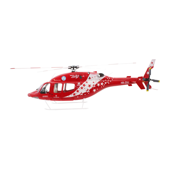
- Page 1 ll 42 29™ ™ Ma nual stribut ted by CCPM SC CALE RC H HELICOPT...
- Page 2 ompactor r 700 Man nual – Be ell 429™ elease 1.0 April 2013 ell, emblem ms, logos, a and body d esigns are trademark ks of Textro on Innovat tions c. and are used unde r license b y Roban Lt oban Limite ryriver Indu ustrial Zone...
-
Page 3: Specifications
SPECIFICATIONS Body length: 1680mm Length incl. rotors: 1850mm Width: 655mm Height: 465mm Main rotor diameter: 1560mm Main blade length: 700mm Tail rotor diameter: 280mm Tail blade length: 105mm Main shaft diameter: 12mm Tail shaft diameter: Spindle diameter: Battery compartment: 2x 60x60x180mm Motor:* 1x 750MX 450KV brushless outrunner, 12S capable Speed controller:*... -
Page 4: Important Notes
IMPORTANT NOTES *This radio controlled helicopter is not a toy. *This radio controlled helicopter can be very dangerous. *This radio controlled helicopter is a technically complex device which has to be built and handled very carefully. *This radio controlled helicopter must be built following these instructions. This manual provides the necessary information to correctly assemble the model. - Page 5 ONTENTS: 1 – Bal l link 2 – Tail tube hol lder 3 – Servo o holder 4 – M Motor belt pu ulley 5 – Tail rot tor assy 6 – Main rotor a 7 – Tail shaf ft bearings 8 –...
- Page 6 7 – Screws A A3x24 4pcs 38 – S Screw M3x16 6 6pcs 39 – Screw A A1,7x6 9pcs 40 – S Screw A2x8 6pcs – Wodden w washers 6pcs 42 – S Screw A3x16 6 4pcs 43 – Washer r 3x8 10pcs 44 –...
- Page 7 DDITIONA AL COMPO ONENTS R REQUIRE TOOLS, L LUBRICAN NTS, ADH HESIVES *Elec ctric Motor: *Generic plie S 12S – 400 6 600Kv, *Hexagonal d driver, size 1.5 5, 2, 2.5, 3, 4m nion shaft diam meter 6mm *4mm T Wre ench *Spe eed controller...
- Page 8 sembly Sc cale Fuse elage Prior r to installing the mechanic cs into the fus elage, please prepare the f fuselage accor rding to the fo ollowing steps insta allation into th he fuselage m ost of the hel icopter mech anic become inaccessible.
- Page 9 Insta all the seats as s shown with epoxy glue. Install the wi ndshield as sh hown. yright@2013 3 - Roban Lim mited – All rig ghts reserved d...
- Page 10 sembly M Mechanics mechanics are e almost entir rely preassem mbled and split t up into four sections: roto orhead, main frame, tail fra ame and tail t ube. Prior r to the insta allation into t the scale fuse elage, the me echanics have e to be entire...
- Page 11 ep 3 – Tai l Servo In nstallatio First of all, mou nt the holde er frame (70 00097) onto o the on both end ds of the tail l rotor contr ol rod. Distri ibute the boom m holders (70 0 00098) using g screw M3x8 8.
- Page 12 ep 5 – Adj just swas shplate lin nkages linkages from m the L Levers s to the swash h plate have t to be set a at correct len ngth. Distance es are uniball center to un niball cent er: 1=35mm ep 6 –...
- Page 13 Step 7 – Electrical Wiring and Setup The mechanics have to be fully electrically setup and adjusted ATTENTION ! prior to installation into the fuselage. As the use of a 12S (44.4V) setup is necessary, we strongly recommend to run the When using the a pitch gauge to adjust correct CP travels, control equipment on a separate 2S Lipo battery and BEC for make sure that the gauge lines up with the flat surface of...
- Page 14 ep 8 – Inst tallation of mecha anics unt the four L L brackets (60 0UH1 003) on nto both side es of Unmount the e entire tail ro otor frame fr rom the tail b box again. main frame as shown.
- Page 15 Insta all the tail stru ut into the tail l fin as shown Install the aft t cover as show Install the tai l assy on the t tail boom as s shown. Insta all the tail fin o on the tail fus selage as show Install the ve rtical and hor...
- Page 16 Insta all the LED (52 2) on the right t side wing Install the LED D (53) on the left side wing Fix the mecha anics with scr ews (43) and brackets (38) inside the fuselage. Insta all the wings u using epoxy gl Insta all the top hat...
- Page 17 Insta all antennas (3 31) as shown. Install antenn na as shown Insta all windshield wipers as sho Install antenn na as shown. Connect the L LED controller r to the LED li ghts. Insta all antennas a s shown.
- Page 18 ep 10 Ba attery ins tallation battery comp partment cons sists of a conv enient and se ecure wooden structure, a b battery drawe er. Oven the h hatch lock first t (move the s stowaway bac ckwards, then n simply open the hatch to a access the bat ttery compart...
- Page 19 pendix A A – Explos sion Draw wings yright@2013 3 - Roban Lim mited – All rig ghts reserved...
- Page 20 Copyright@2013 3 - Roban Lim m ited – All rig g hts reserved d...
- Page 21 Copyright@2013 3 - Roban Lim m ited – All rig g hts reserved d...
- Page 22 Copyright@2013 3 - Roban Lim m ited – All rig g hts reserved d...
- Page 23 Copyright@2013 3 - Roban Lim m ited – All rig g hts reserved d...
- Page 24 Copyright@2013 3 - Roban Lim m ited – All rig g hts reserved d...
- Page 25 Copyright@2013 3 - Roban Lim m ited – All rig g hts reserved d...
- Page 26 Copyright@2013 3 - Roban Lim m ited – All rig g hts reserved d...
- Page 27 Cop yright@2013 3 - Roban Lim m ited – All rig g hts reserved d...
- Page 28 pendix B – Sparep parts yright@2013 3 - Roban Lim mited – All rig ghts reserved d...
- Page 29 Copyright@2013 3 - Roban Lim m ited – All rig g hts reserved d...
- Page 30 Copyright@2013 3 - Roban Lim m ited – All rig g hts reserved d...
- Page 31 Copyright@2013 3 - Roban Lim m ited – All rig g hts reserved d...
- Page 32 Cop yright@2013 3 - Roban Lim m ited – All rig g hts reserved d...
-
Page 33: Appendix C - Sparepart List
Appendix C – Sparepart List RCH 70 001 1 JJ 70 00147 Sideframes Seitenrahmen 1 JJ 70 00148 Aft frame hintere Platte 1 JJ 70 00149 Bottom frame Bodenplatte 1 JJ 70 00150 Fwd frame vordere Platte RCH 70 002 1 JJ 70 00099 Distancer 6x62 Distanzstück 6x62... - Page 34 RCH 70 025 1 JJ 70 00020 Washer 3x9x1.5 Beilagscheibe 3x9x1.5 1 JJ 70 00021 Bearing 3x7x3 Kugellager 3x7x3 1 JJ 70 00022 Washer 3x4.5x1.1 Beilagscheibe 3x4.5x1.1 1 JJ 70 00023 L Lever L Hebel 1 JJ 70 00019 Screw M3x25 Schraube M3x25 1 JJ 70 00018 Self Locking Nut M3...
- Page 35 RCH 70 047 1 60 WJ 00010 Washer 5x7x5.7 Hülse 5x7x5.7 1 60 WJ 00011 Washer 5x7x2.1 Beilagscheibe 5x7x2.1 1 60 WJ 00006 Tail shaft 2 blade Heckwelle 2 Blatt RCH 70 048 1 JJ 70 00121 Washer 16x18x9.6 Hülse 16x18x9.6 1 60 WJ 00002 Tail frame gear Kegelrad Heck...
- Page 36 RCH 70 079 1 JJ 70 00090 rotor head 4 blade top Rotorkopf 4 Blatt oben 1 JJ 70 00133 rotor head 4 blade bottom Rotorkopf 4 Blatt unten RCH 70 080 1 JJ 70 00100 Bearing 7x11x3 Kugellager 7x11x3 RCH 70 081 1 JJ 70 00101 Bearing 3x6x2.5...
- Page 37 NOTES: Copyright@2013 - Roban Limited – All rights reserved...
- Page 38 Copyright@2013 - Roban Limited – All rights reserved...
Need help?
Do you have a question about the Roban Bell 429 Compactor 700 and is the answer not in the manual?
Questions and answers