Table of Contents
Advertisement
User Manual
for eConnect
®
PDU and
Electronic
Lock Kit
Reference Sales Model EA-XXXX
Regulatory Model K-XXXX
Version 2
February 2020
While every effort has been made to ensure the accuracy of all information, CPI does not accept liability for any
errors or omissions and reserves the right to change information and descriptions of listed services and products.
©2020 Chatsworth Products, Inc. All rights reserved. Chatsworth Products, Clik-Nut, CPI, CPI Passive Cooling,
eConnect, Evolution, GlobalFrame, MegaFrame, Motive, QuadraRack, RMR, Saf-T-Grip, Secure Array,
SeismicFrame, SlimFrame, TeraFrame and Velocity are federally registered trademarks of Chatsworth Products.
CUBE-iT, EuroFrame and Simply Efficient are trademarks of Chatsworth Products.
800-834-4969
All other trademarks belong to their respective companies. Rev2. 02/20 MKT-60020-720
chatsworth.com
techsupport@chatsworth.com
CPI User Manual for eConnect PDU and Electronic Lock Kit
02/20.v2
1
Advertisement
Table of Contents

Related Manuals for Chatsworth Products eConnect EA Series

Summary of Contents for Chatsworth Products eConnect EA Series
- Page 1 ©2020 Chatsworth Products, Inc. All rights reserved. Chatsworth Products, Clik-Nut, CPI, CPI Passive Cooling, eConnect, Evolution, GlobalFrame, MegaFrame, Motive, QuadraRack, RMR, Saf-T-Grip, Secure Array, SeismicFrame, SlimFrame, TeraFrame and Velocity are federally registered trademarks of Chatsworth Products.
-
Page 2: Table Of Contents
TABLE OF CONTENTS Introduction ................. 3 Product Features ..............4 Product Labeling and Certifications ........6 PDU Models ............... 7 Installation Checklist for PDUs and Electronic Lock Kit ..8 Installation Guide ............... 9 Using the Local Display ........... 11 Display Setup .............. -
Page 3: Introduction
Legal Information The information contained in this guide is subject to change without notice. Chatsworth Products, Inc. (CPI) shall not be liable for technical or editorial errors or omissions contained herein; nor is it liable for any injury, loss, or incidental or consequential damages resulting from the furnishing, performance or use of this material and equipment. -
Page 4: Product Features
Primary Role: The role that is assigned to the PDU that is attached to the network and serves as the beginning of the Secure Array. This PDU should have a level of functionality that is equal to or higher than that of all the remaining PDUs within the array. - Page 5 Mounting: Mounting style: 2 x Tool-less Buttons on the PDU rear cover Distances: 61.25” (1556 mm) and 64.75” (1645 mm) apart Positions: 4 mounting positions (A1, A2, B1, B2) Field-replaceable Main Control Module The Main Control Module can be replaced at the customer site without having to return the entire PDU LCD local display with push button control: Dimension: 1.5”...
-
Page 6: Product Labeling And Certifications
Temp/Humidity sensor will be plugged into either standard USB1 or USB2 port Secure Array/PDU Linking/Serial Port: Connector type: (2) RJ45 (1) link-in/serial combo port (1) link-out port for serial communication and PDU linking using a Cat 5/6 cable PRODUCT LABELING AND CERTIFICATIONS The presence of the CE Mark on equipment means that it has been designed, tested and certified as complying with all applicable European Union (CE) regulations and recommendations. -
Page 7: Pdu Models
PDU MODELS Tip: See how much savings you can obtain by taking advantage of the CPI User Manual for eConnect PDU and Electronic Lock Kit 02/20.v2... - Page 8 INSTALLATION CHECKLIST For eConnect PDUs and Electronic Lock Kit Safety Warnings and Cautions • DO NOT OPEN THE CHASSIS of an eConnect PDU. There are no user serviceable parts within an eConnect PDU, except for eConnect Controller Module. Opening or removing covers, receptacle plates, or other access points may expose you to dangerous shock hazards or other risks.
-
Page 9: Installation Guide
INSTALLATION GUIDE Preparation: • Prepare a plan identifying where each rack device is to be connected to the PDU receptacle. For ease of power cord management, if you are installing a vertically mounted PDU, it is recommended to connect the rack device to the receptacle that is approximately at the same height. - Page 10 Locking Outlets: The locking receptacles feature a locking lever that engages with IEC corded plugs. To engage, insert the IEC plug into the receptacle until you hear a click. Ensure the locking lever is engaged by squeezing the lever and IEC plug together. To disengage, pull the locking lever away from the IEC plug until it holds in the open position.
-
Page 11: Using The Local Display
Energizing the PDU • Attach the input power cord to a matching power source. • The PDU status light will blink Green for about 90 seconds as the PDU is booting up. • A solid Green status light will follow with the LCD display coming on and displaying all zeroes. - Page 12 Basic Menu Navigation The legend below explains the meaning of each button on the PDU display: Menu button/icon definitions and functions Go to the Main Menu. Note: In PDUs in the Secure Array, the blue icon — —turns green— Note: The home icon turns purple during a firmware upgrade—...
- Page 13 Monitoring PDU Conditions The main screen on single-phase PDUs list total amperage, voltage and power usage by equipment attached to the PDU. The main screen on three phase PDUs lists total voltage and power usage by equipment attached to the PDU. Single-phase PDU Three-phase PDU From the Main menu press:...
- Page 14 From the Main menu press: Left button to set up the PDU Middle button to scroll through the remaining screens Right button to go back to the Main Menu After scrolling through the branch/phase screens, the PDU will display the Environment summary screen.
- Page 15 From the Main menu press: Left button to set up the PDU Middle button to go to the next data screen Right button to go back to the Main Menu Alarms When any alarm or warning threshold is hit, the Alarms summary will be displayed before the PDU Total values when the Home Icon is selected.
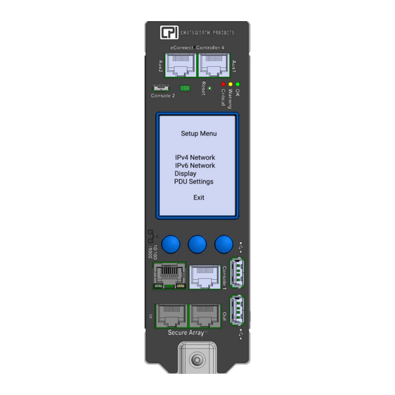
- Page 16 Additionally, when there is an alarm, the out-of-range measurements are highlighted on the respective summary screen, and the LED next to the display will flash. Network Configuration Select the Left Button to access the PDU Setup Menu Click on: Left button to traverse down the list of options Middle button to select the highlighted option Right button to traverse up the list of options Select Exit to exit this screen...
- Page 17 Click on: Left button to traverse down the list of options Middle button to select the highlighted option Right button to traverse up the list of options Select Save or Cancel to exit this screen Save updates IP information immediately Cancel makes no changes to the setup Return to the Setup Menu.
-
Page 18: Display Setup
Display Setup Return to the Setup Menu. Use the Left button to select Display. Click on middle button to set up the Display Click on: Left button to traverse down the list of options Middle button to select the highlighted option Right button to traverse up the list of options Timeout –... -
Page 19: Pdu Settings
PDU Settings Return to the Setup Menu. Use the left button to select PDU Settings. Click on middle button to set up advanced info for the PDU Optional - Click on: Left button to traverse down the list of options Middle button to select the highlighted option Right button to traverse up the list of options Role –... - Page 20 Network Only – Will immediately reset the IP address back to the default address (192.168.123.123) and reboot the main communications module. Outlets will not lose power, but you will lose your network connection and monitoring during reboot. Config Only – Will immediately reset PDU and outlet names, alarm thresholds, etc.
-
Page 21: Update Firmware
Update Firmware Click on middle button to update firmware for the PDU. Optional - Click on: Left button to traverse down the list of options Middle button to select the highlighted option Right button to traverse up the list of options Sample of Updating screen Sample of Failed updating CPI User Manual for eConnect PDU and Electronic Lock Kit... -
Page 22: Pdu Model Information
PDU Model Information Optional - Click on: Left button to traverse down the list of options Middle button to select the highlighted option Right button to traverse up the list of options Click on middle button to traverse back to the PDU Settings Menu. Click on middle button to traverse back to the PDU Settings Menu. -
Page 23: Using The Built-In Web Server Application
USING THE BUILT-IN WEB SERVER APPLICATION Login All eConnect PDUs, excluding Basic models, are shipped with: A 1 GB Ethernet connection and built-in Web Server Application Default IP address: 192.168.123.123 Default Username/Password: admin/admin You can access the PDU using the default IP address, or you can use the LCD Local display (see page 31) to change the default IP address to the appropriate IP address. - Page 24 To assign a Time Server, click on the Settings tab, Network sub menu. Scroll down the page to the heading Time Servers. Enter the IP Address of the RFC or NTP Time Server. The PDU must have network access to the time server. For detailed network setup, see Settings –...
- Page 25 Click on Sync PDU time and then Save button to update the clock on the PDU using the browser date and time, or manually set the time with the drop boxes. Note that if you perform a firmware upgrade, the PDU will reboot and the time will need to be manually reset, unless you have assigned Time Server to the PDU.
- Page 26 Status – Overview Click on the Status tab, Overview sub menu to view circuit, sensor, input and outlet status. All models present branch circuit status and sensor status (when attached). The screenshot below shows a single-breaker model with PDU Branch Status for branch circuits (CB1).
- Page 27 When the Electronic Lock Kit is attached to the PDU, the doors and the locks will be displayed under Front Door Status and Rear Door Status. Door status: • Not Configured: Lock is not enabled. • Closed: Door is closed. •...
- Page 28 Monitored Pro, Switched, and Switched Pro models will also present per outlet status. The image below shows a Switched Pro model. Switched models do not include Current, Voltage, Power or Energy values. Monitored Pro models do not include Status or Control values.
- Page 29 Status – Alarms Click on Alarms to view a summary of Alarm messages, if there are any present: Warning thresholds are indicated by a yellow-colored rectangular alarm status symbol. Critical thresholds are indicated by a red-colored rectangular alarm status symbol. Note: The CPI alerts and notification system can be broken down into a few components: •...
- Page 30 Outlet – Overview Monitored Pro, Switched and Switched Pro models, Click on Outlet, Overview tab to view Outlet Status on the PDU: Switched and Switched Pro models, you can turn outlets on or off by clicking the checkbox under the Control column. The indicator in the Status column will change as the outlet switches on or off.
- Page 31 Outlet – Setup To name and enter alarm limits for a specific Outlet, from the Outlet tab, click on the Set Up sub menu, and use the drop-down list to select the outlet: Switched and Switched Pro models include settings for Outlet ON Delay and Outlet Cycle Delay, allowing you to specify a delay when power is cycled.
-
Page 32: Outlet - Groups
Outlet – Groups To create a group of outlets from a single PDU or multiple PDUs that are linked together, click on the Outlet tab, click on the Groups submenu, then click on New Group: Name the Group, select PDU(s) and Outlets to be grouped and click on Save button: To view, edit or remove an existing group, click on View or Edit or Remove under Action in the Outlet, Groups table: View provides Group Status. -
Page 33: Econnect Cabinet Access Control - Overview
eConnect Cabinet Access Control – Overview *Only applicable for Vertical eConnect PDUs with Auxiliary Ports. Go to page 35 to jump to Logging tab. CPI User Manual for eConnect PDU and Electronic Lock Kit 02/20.v2... -
Page 34: Cabinet Access - Settings
Cabinet Access – Settings Enter the Cabinet Lock Open Time: 1 – 30 seconds. The default value is 5 seconds Enter Cabinet Door Open Alarm Time: 1 – 240 mins. The default value is 10 minutes Check box to enable Front or/and Rear Lock(s) where applicable Click on Save to save the configured data. -
Page 35: Cabinet Access - Radius Card Settings
Cabinet Access – Radius Card Settings Check the Enable Radius Card Authentication box to be able to enter the server information Check the Use IPv6 box. If applicable click Save CPI User Manual for eConnect PDU and Electronic Lock Kit 02/20.v2... -
Page 36: Logging - Overview
Logging – Overview Select Syslog Filter by checking the check box(es) and click on the Reload Entries button to obtain up-to-date information. CPI User Manual for eConnect PDU and Electronic Lock Kit 02/20.v2... -
Page 37: Logging - Export Logs
Logging – Export Logs Select type of file and select the log file to be exported. Click on DOWNLOAD to download selected file to the connecting computer. Click on TRANSFER TO SERVER to save the file on the designated storage server. Click on DELETE to remove the save file from the PDU CPI User Manual for eConnect PDU and Electronic Lock Kit 02/20.v2... -
Page 38: Logging - Settings
Logging – Settings Metric Data Logging: Check Enable Logging check box to begin capturing data on the PDU internal memory. Input the desired interval and Log Full Warning Level percentage. Event Logging Settings: Log Identity and Log Facilities are preset on the PDU memory system. Pick any Log Local to store data locally. -
Page 39: Notification - Thresholds
Notification - Thresholds Branch Thresholds Input all desired limitations to be set as thresholds. Click on Save. Scroll down to input other thresholds. Environmental Thresholds Input all desired limitations to be set as thresholds. Click on Save. Scroll down to input other thresholds. - Page 40 Environmental Thresholds (Continued) For Switched and Switched Pro models only: CPI User Manual for eConnect PDU and Electronic Lock Kit 02/20.v2...
-
Page 41: Notification - Routing
Notification - Routing Select method(s) of notifications for Branch Voltage and Branch Current by checking the check box(es): Log, Trap, Email Check the Log boxes to check what kinds of events provoke a log entry. Then, check the boxes for the events you want to Trap. With regards to emails, if a particular alarm becomes active, the PDU will send an email in response to this alarm becoming active, if configured to do so. - Page 42 Select method(s) of notifications for Outlet, Temperature, Humidity if applicable by checking the check box(es): Log, Trap, Email. Scroll down for more notification settings. Select method(s) of notifications for Door, Lock, and PDU if applicable by checking the check box(es): Log, Trap, Email. Click on Save to save the input data.
-
Page 43: Settings - Pdu
Settings – PDU Enter desired PDU Name and Location. The PDU Name is displayed in the summary information at the top of each web interface screen and on the PDU’s LCD screen. Out of Service checkbox: Check this box to deactivate the Electronic Lock Kit alarms if a PDU goes offline or becomes “unlinked.”... - Page 44 Primary PDU checkbox: eConnect PDUs can be linked together through a Secure Array to share a single IP address through a single network connection. Check this box for the PDU with the highest-level functionality. For several PDUs that have the highest level of functionality, check the box for the one that has the highest number of outlets.
-
Page 45: Settings - Pdu - Clone
Settings – PDU - Clone Data from the Primary PDU can be cloned to the other PDUs in the Secure Array by checking the desired parameters and selecting the PDUs to be cloned. You can designate one of the linked PDUs as an Alternate PDU. The Alternate PDU serves as a backup to the Primary PDU. -
Page 46: Settings - Environmental
Settings - Environmental Select choice of temperature unit, enter name for the temperature and humidity sensors. Click on Save. CPI User Manual for eConnect PDU and Electronic Lock Kit 02/20.v2... -
Page 47: Settings - Network
Settings – Network • Network - Using the Enable Protocols combo box, select the Network Protocol(s). Enter data for IPv4 and/or IPv6 Networking. • Time Servers – Designate a time server as the source for time after each reboot (requires a network connection). As an alternative, you can manually set the time from the Administration tab, Advanced sub menu. -
Page 48: Settings - Snmp
Settings – SNMP Enter data for SNMP v1, v2c or v3 settings. Enter the IP Addresses you want to send traps to. Click on Save to save all entered data. CPI User Manual for eConnect PDU and Electronic Lock Kit 02/20.v2... -
Page 49: Settings - Emails
Settings – Emails The PDU does not include a mail server. In order to provide email notifications for the PDU, you must first setup an email account for the PDU on an accessible mail server. • SMTP Mail Server – the mail server where the account resides, ex: smtp.google.com. •... -
Page 50: Administration - User Management
Administration – User Management Click on Create User to add a new user. Input the username and password and click on Create. To edit an existing user. Click on Edit for that username. CPI User Manual for eConnect PDU and Electronic Lock Kit 02/20.v2... - Page 51 Change the necessary information. Input the Smart Card ID for the Electronic Lock Kit. If you don’t know your Smart Card ID, see Appendix on Page 61. The same information should be input for both the Primary and Alternate PDU to assure the same logging authority will be carried through.
-
Page 52: Administration - Radius Authentication
Administration – Radius Authentication For network/website authentication using Radius Authentication, enter the necessary information and Save. Note that users will need to be added under the Local User List to have Control or Admin capabilities. Administration – LDAP Authentication For network/website authentication using LDAP Authentication, enter the necessary information and Save. -
Page 53: Administration - Advanced
Administration – Advanced PDU Info includes serial number and MAC address. Model number and firmware version are also displayed in the gray summary box at the top of each screen. Verify the Time and Date Settings to ensure date/time stamps on logs and alarms are correct. -
Page 54: Administration - Upgrade Firmware
• Reset All – Resets all fields to factory defaults. To reset to factory defaults, select the appropriate radial button. Review the warning message. Click the Apply Defaults button to apply selected defaults. Resets are applied immediately. Administration – Upgrade Firmware CPI User Manual for eConnect PDU and Electronic Lock Kit 02/20.v2... - Page 55 Post the downloaded firmware to an accessible HTTPS/FTP or TFTP directory or to a directory on a computer on the same network subnet as the PDU. For HTTPS/FTP or TFTP upgrade, enter HTTPS/FTP or TFTP data. Click on the Test button to assure the remote site can be reached. Click on the Upgrade button to perform the upgrade.
-
Page 56: Using The Comand Line Interface (Cli)
USING THE APPLICATION PROGRAMING INTERFACE (API) Refer to this link to get API instructions (www.chatsworth.com/en-us/power- management/resources/design-tools/software USING THE COMAND LINE INTERFACE (CLI) The Command line allows you to make a direct connection to the computer. You’ll need a console serial cable to connect between the computer and the PDU (Go to page 5 console location on PDU controller). - Page 57 • If the problem persists, verify that the units in the PRIMARY and ALTERNATE roles have the highest number of outlets within their functionality. No Ethernet Connection: • Verify connection with a ping tool from any computer in the network. •...
-
Page 58: Replacing The Controller Module
REPLACING THE CONTROLLER MODULE IMPORTANT NOTE: The PDU must be disconnected from the power source before and placed on a leveled surface before controller module replacement. 1. Use an antistatic strap while replacing the controller. Unfasten the controller hold down screw using a T10 Torx®... - Page 59 4. After the CAN Bus connector is removed, the controller can be lifted vertically away from the PDU. To transfer PDU identify, configuration and settings for the PDU, swap the SD card on the back of the controller board from the old controller to the new controller.
- Page 60 7. As you rotate the controller down to ~45 degrees, guide the CAN Bus cable with your finger to ensure the cable goes into the slot provided below the controller within the PDU 8. When the controller is resting on top of the PDU, start to fasten the hold down screw on the front edge of the controller until the unit is secure CPI User Manual for eConnect PDU and Electronic Lock Kit...
-
Page 61: Appendix
APPENDIX Regulatory Information: FCC Part 15, Class A EN 55022 RoHS Compliant UL &cUL Listed IEC 62368 Operating Temperature: 32 - 149˚F (0 - 65˚C) at Input Power Rating (kW) Operating non- condensing relative Humidity: 5 - 95% Operating Elevation: 0-10000 ft (0-3000 m) Storage Temperature: -13 - 149˚F (-25 - 65˚C) Storage Relative Humidity: 5 - 95% Storage Elevation: 0-50000ft (0-15000 m) -
Page 62: Appendix For Electronic Lock Kit (Econnect)
APPENDIX for Electronic Lock Kit for eConnect Assigning a Smart Card ID As discussed in the section Administration – User Management (page 50), each user may be assigned a unique smart card ID associated with their account that allows the PDU to unlock the Electronic Lock Kit mechanism (if installed) when a smart card is presented to the cabinet door lock. - Page 63 CPI User Manual for eConnect PDU and Electronic Lock Kit 02/20.v2...
- Page 64 The second method to interrogate an unknown smart card is to utilize the pcProx Plus ® external card reader, CPI part number 36653-001, and a windows-based computer that is logged on to the eConnect web interface. The external card reader plugs into any available USB port on the computer and will generate “keystrokes”...
- Page 65 CPI User Manual for eConnect PDU and Electronic Lock Kit 02/20.v2...
- Page 66 Determining what Card Profile to use The pcProx Plus Card enrollment reader must tailored to the RFID Card Type that will be ® used with the Electronic Lock Kit system. If the card type is one of the Desfire, HiD iClass, Mifare Classic or Prox, please proceed to Programming the pcProx Plus reader on ®...
- Page 67 After selecting Card Analyzer from the menu, place the ID card on the reader and press the Learn Card button: The reader will then scan through several card types. When a compatible card type is found the Card Type box will show the type of card. CPI User Manual for eConnect PDU and Electronic Lock Kit 02/20.v2...
- Page 68 After determining the type, the user is ready to write the proper settings to the pcProx Plus ® reader. Programming the pcProx Plus reader ® In order for the pcProx Plus reader to be compatible with the Electronic Lock Kit, the card ®...
- Page 69 CPI User Manual for eConnect PDU and Electronic Lock Kit 02/20.v2...
- Page 70 Common RFID Card Types and Reader Format Settings Desfire Card: CPI User Manual for eConnect PDU and Electronic Lock Kit 02/20.v2...
- Page 71 HiD iClass Card: CPI User Manual for eConnect PDU and Electronic Lock Kit 02/20.v2...
- Page 72 MiFare Classic Card: CPI User Manual for eConnect PDU and Electronic Lock Kit 02/20.v2...
- Page 73 Prox Card: Prox cards require an additional settings in the Wiegand to keystroke data format box, as shown below: CPI User Manual for eConnect PDU and Electronic Lock Kit 02/20.v2...
- Page 74 APPENDIX 2 – Command Line Interface CPI User Manual for eConnect PDU and Electronic Lock Kit 02/20.v2...
Need help?
Do you have a question about the eConnect EA Series and is the answer not in the manual?
Questions and answers