Table of Contents
Advertisement
Quick Links
Installation instructions
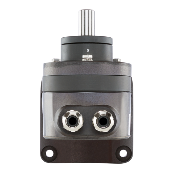
Angle position transmitter
Type RT-2
Marine bridge instrumentation
4189350013C (UK)
•
Analogue output
for direct connection of one or more indicators
•
Measuring output:
DC current signal 0..20mA or 4..20mA
•
Potentiometer for adjusting span and zero
•
Angle position 0..90
•
Continuous shaft rotation
DEIF A/S
Frisenborgvej 33, DK-7800 Skive Fax:
Denmark
°
°
or 0..140
Tel.:
(+45) 9614 9614
(+45) 9614 9615
E-mail: deif@deif.com
Advertisement
Table of Contents

Summary of Contents for Deif RT-2
- Page 1 Installation instructions Angle position transmitter Type RT-2 Marine bridge instrumentation 4189350013C (UK) • Analogue output for direct connection of one or more indicators • Measuring output: DC current signal 0..20mA or 4..20mA • Potentiometer for adjusting span and zero •...
-
Page 2: Brief Description
1. Brief description The RT-2 converts the position angle of a shaft into a load-independent direct current signal, proportional to the angle position. 2. Technical data Measuring input 0..90° or 0..140° (span adjustment –30/+5% of full scale) Measuring output Output variable I Load-independent DC current, proportional to the input angle. - Page 3 Installation instructions, RT-2 Power supply H DC voltage: 12...33V (Polarity reversal protection. The voltage must not fall below 12V.) Max. residual ripple: 10% p.p. Max. current consumption: Approx. 5mA + I Mechanical withstand Permissible vibration: 0...200Hz, 10 g continuous, 15 g for 2 h 200...500Hz,...
- Page 4 Similarly, it is advisable to elongate the three holes (6.5 mm diam.) drilled for “directly” mounted version (see upper drilling and cut-out diagram in Table 1). Tel.: (+45) 9614 9614 • Fax: (+45) 9614 9615 • E-mail: deif@deif.com Page 4 of 11...
-
Page 5: Electrical Connections
Note that, ..the data required to carry out the prescribed measurement must correspond to those marked on the nameplate (Fig. 2) of RT-2 (measuring input, measuring output, power supply)! ... the total voltage drop do not exceed the supply voltage H[V], see “Measuring output”... - Page 6 (4.1) and (4.2) according to the wiring diagram (Fig. 3). Then fit the gland seal, pinch ring and nut. Tighten the gland nut and replace the cover. Tel.: (+45) 9614 9614 • Fax: (+45) 9614 9615 • E-mail: deif@deif.com Page 6 of 11...
- Page 7 First, switch on the power supply to the transmitter. Remove the 3 screws (3.2) and the cover (3.1) (Fig 3). Place the measured devide at its zero position, i.e. the position at which the RT-2 should produce 0 mA (three or four-wire connection), respectively 4 mA (two-wire connection) at its output.
- Page 8 If, however, a transmitter be changed from one to the other (see wiring diagrams in Fig. 4), the beginning and end of the measuring range must be readjusted. Tel.: (+45) 9614 9614 • Fax: (+45) 9614 9615 • E-mail: deif@deif.com Page 8 of 11...
-
Page 9: Mechanical Connection
Installation instructions, RT-2 8. Mechanical connection Mounting of linkage on the RT-2. Mounting of ball joint. Page 9 of 11 4189350013C (UK) - Page 10 Cutting the length of the adjustable lever. After adjusting the length (shorten when necessary), fix using mechanical means (welding, gluing, pinning). Page 10 of 11 Tel.: (+45) 9614 9614 • Fax: (+45) 9614 9615 • E-mail: deif@deif.com...
-
Page 11: Dimensional Drawings
Installation instructions, RT-2 9. Dimensional drawings RT-2 with screw terminals and glands. Without bracket RT-2 with screw terminals and glands. With bracket. Errors and changes excepted Page 11 of 11 4189350013C (UK)
Need help?
Do you have a question about the RT-2 and is the answer not in the manual?
Questions and answers