
Summary of Contents for SCS P4dragon DR-7800
- Page 1 Deutsch / English Installationsanleitung Version 1.0 06 / 2011 Installation Guide Special Communications Systems...
- Page 2 Further, SCS reserves the right to revise this publication, hardware, and software, and to make changes from time to time in the content thereof without the obligation of SCS to notify any persons of such revisions or changes.
- Page 3 Special Communications Systems Model P4dragon DR7800 Federal Communications Commission (FCC) Statement This equipment has been tested by a FCC accredited testing facility and found to comply with the limits for Class B Digital Device, persuant to Part 15 of the FCC rules. These rules are designed to provide reasonable protection against harmful interference in a residential installation.
- Page 4 Deutsch Seite 1 English Page 47...
- Page 6 Vielen Dank, dass Sie sich für ein SCS P4dragon DR7800 Hochgeschwindigkeits-HF-Radio- Modem entschieden haben. SCS-Modems sind das Original, direkt von den PACTOR Entwicklern. Nur bei SCS erhalten Sie den optimalen Support. Das geballte Wissen der PACTOR-Entwickler steht zu Ihrer Verfügung.
- Page 7 1. Einleitung Die SCS CD-ROM Auf der beiliegenden SCS-CD-ROM finden Sie Software und Tools, welche Sie für den Betrieb des P4dragon benötigen, sowie weitere wertvolle Tipps und Informationen rund um PACTOR. Zusätzlich befinden sich auf der CD der USB-Treiber und das PDF-Handbuch für...
-
Page 8: Die Programme
Programme auf der SCS-CD gesammelt und verfügbar gemacht. Da diese Programme nicht von SCS entwickelt wurden, kann SCS auch keine Unterstützung dafür leisten. Falls Sie Fragen oder Probleme mit einem dieser Programme haben, wenden Sie sich bitte direkt an den jeweiligen Autor. - Page 9 über weite Entfernungen zu verteilen. SCSupdate Obgleich auch diverse Fremdsoftware in der Lage ist, bei SCS Modems ein Firmware durchzuführen, ist SCSupdate das empfohlene Programm hierfür, da es direkt von SCS entwickelt wurde. Wenn Sie auf der SCS-Webseite eine neuere Firmware finden als die, welche in Ihrem Gerät installiert ist, können Sie diese von dort herunter laden und mit Hilfe...
- Page 10 Im Jahr 1995 wurden Digitale Signalprozessoren (DSP) zu akzeptablen Preisen verfügbar, und diese neue Technologie wurde von SCS dazu verwendet, um die nächste Entwicklungsstufe einzuläuten: PACTOR-2. Als Modulationsart wurde Phasenmodulation (PSK) gewählt, und effiziente Fehlerkorrektursysteme wurden hinzugefügt. Das Ganze sollte noch in einen 500 Hz Kanal passen und sich adaptiv an dessen Qualität anpassen, um immer die höchste mögliche...
- Page 11 3. Die PACTOR Modi • Niedriger Crestfaktor (hohe Durchschnittsleistung). • Hohe spektrale Effizienz, sehr gute Ausnutzung der Bandbreite. • Volle Abwärtskompatibilität zu bestehenden PACTOR-1/2-Netzen. PACTOR-4 (P4) Da die Leistungsfähigkeit von Digitalen Signalprozessoren im Laufe der Jahre enorm gestiegen ist, schien möglich, neuen, sehr...
- Page 12 140 Hz im 20-m-Band. Die „PACTOR-IP-Bridge“ ( später verfügbar im DR7800 Die PACTOR-IP-Bridge (PIB) ist ein neues, von SCS entwickeltes Netzwerk-Integrations- Protokoll, das mehrere Unterprotokolle zu einer funktionalen und einfach handzuhabenden Einheit verbindet. Die im Internet dominierenden Protokolle TCP/IP sowie das Point-to-Point- Protokoll (PPP), das sich als Standard für den Verbindungsaufbau für Internetanwendungen...
- Page 13 3. Die PACTOR Modi zwischen dem PC und dem P4dragon ergibt sich ein weiterer entscheidender Vorteil: PPP war bisher aufgrund der sehr kurzen „Timeouts" kaum über langsame Kommunikationsstrecken mit relativ großen Verzögerungen einsetzbar - diese „Timeout"-Problematik entfällt gänzlich durch die PACTOR-IP-Bridge. Zusammenfassend die Eigenschaften der PIB: •...
- Page 14 Sollten Sie doch einmal ein SCS-Produkt zur Reparatur einschicken müssen, beachten Sie bitte folgende Hinweise: • Nehmen Sie grundsätzlich immer Kontakt mit SCS per Email auf bevor Sie ein Modem zur Reparatur einsenden. Sie werden wichtige Sendungsinstruktionen erhalten, die Sie befolgen müssen, damit sichergestellt werden kann, dass ein Gerät gut bei uns ankommt.
- Page 15 4. Support...
-
Page 16: Installation
5. Installation 5 Installation Die Installation des P4dragon ist einfach. Sie müssen lediglich die Kabel zum Rechner, Funkgerät und für die Stromversorgung konfigurieren. Kabel zu gängigen Funkgeräten können Sie ggf. fertig konfiguriert kaufen. Stromversorgung Der P4dragon hat drei Eingänge zur Stromversorgung, die Sie alternative verwenden können. Entweder Sie verwenden die mit „DC-in“... - Page 17 Masse mit anderen Geräten, die am Modem angeschlossen sind. Um den USB-Anschluss zu verwenden, muss ein passender Treiber auf dem Computer installiert werden. Dieser befindet sich auf der SCS -CD, welche Sie zusammen mit dem Gerät erhalten haben.
- Page 18 Üblicherweise werden Treiber und Software zur Bedienung von Bluetooth (Bluetooth-Manager) automatisch von der mitgelieferten CD installiert. SCS liefert keine Bluetooth-Software auf der SCS-CD mit! Verwenden Sie bitte zur Installation die CD des Bluetooth-Stick-Herstellers! In jedem Fall entsteht nach der Installation (ggf.
- Page 19 5. Installation Abbildung 2: Entfernen der Schraubklemmen Den P4dragon öffnen: Entfernen Sie die beiden schwarzen TORX-Schrauben im Plastikrahmen der Frontplatte des Geräts. (Versuchen Sie nicht, das Modem von der Rückseite aus zu öffnen!) Entfernen Sie den Plastikrahmen und kippen Sie die Frontplatte nach unten. Die Frontplatte enthält das Display und hängt an einem Flexprint-Kabel.
- Page 20 5. Installation Als nächsten drücken Sie die drei Haltebolzen in die dafür vorgesehenen Löcher der Modem- Leiterplatte. Die Bolzen haben zwei verschieden geformte Enden: Abbildung 5: Bluetooth Haltebolzen Die “Mainboard” Seite der Bolzen kommt in die Modem-Leiterplatte. Die Bolzen gehen etwas schwer hinein, am besten man benutzt eine Zange für diesen Vorgang, während die Platine auf einem weichen aber stabilen Untergrund liegt.
- Page 21 5. Installation Abbildung 8: Das Bluetooth-Modul installiert Zusammenbau des P4dragon: Nachdem die Installation beendet ist, kann die Leiterplatte wieder in das Gehäuse geschoben werden. Dabei ist darauf zu achten, dass die kleinen, grünen Steckverbinder für „GPS” and „DC-in” ohne sich zu verhaken durch die Rückplatte hindurch treten. Ggf. sind diese mit Hilfe einer Pinzette auszurichten, während die Leiterplatte in die Endlage kommt.
- Page 22 5. Installation Starten Sie die Bluetooth-Manager-Software auf diesem PC. Die Benutzeroberflächen dieser Manager sind abhängig vom Hersteller der Software und vom Betriebssystem des Computers, daher kann hier nur die grundsätzliche Vorgehensweise beschrieben werden. Lassen Sie den Bluetooth-Manager eine Suche nach Bluetooth-Geräten in Reichweite durchführen.
- Page 23 B. das Hostmode-Protokoll oder Anwendungen wie FAX. Für solche Anwendungen können sich die Latenzzeiten einer Internetverbindung störend auswirken. Eine Hostmode-Verbindung über einige 100 km zwischen zwei SCS-Standorten innerhalb Deutschlands wurde schon erfolgreich getestet. Im Zweifelsfall muss man es austesten.
- Page 24 5. Installation Abbildung 10: SER2NET Installation 5.4.3 Konfiguration des SER2NET Nach dem Starten von "HW Virtual serial Port" durch klicken auf das entstandene Symbol müssen einige Einstellungen vorgenommen werden. Das Feld „IP Address“ erfordert die Eingabe der IP-Adresse des P4dragon. Im Feld „Port“ wird der Datenport der Verbindung eingegeben und „Port Name“...
- Page 25 5. Installation Abbildung 11: Eintragen der Port-Nummer Die Angaben im Settings-Tab können bleiben wie sie sind. Andere Eingaben sind nicht nötig. Abbildung 12: SER2NET Konfiguration 5.4.4 Verwendung von SER2NET Nachdem alle Einstellungen wie beschrieben vorgenommen wurden, klicken Sie einfach auf die Schaltfläche Create COM.
- Page 26 5. Installation Abbildung 13: SER2NET Konfiguration Sie sehen nun, dass sich der Status des VSP (Virtual Serial Port) auf Created geändert hat, und der LAN Status zeigt nun Connected. Sobald das Anwenderprogramm, welches den virtuellen COM-Port (in diesem Beispiel COM5) verwendet, gestartet ist, ändert sich der VSP-Status zu Opened, und die Serial-Port- Parameter (Baudrate usw.) werden angezeigt.
- Page 27 5. Installation Um den virtuellen COM-Port wieder zu deaktivieren, ist zuerst die Anwendersoftware zu schließen. Danach kann der COM-Port mit einem Klick auf Delete COM gelöscht werden. Das Modem ist jetzt wieder freigegeben und könnte von einem anderen Benutzer im Netzwerk oder über das Internet verwendet werden.
-
Page 28: Die Anschlüsse
6. Die Anschlüsse 6 Die Anschlüsse Massekonzept und Schirmung Der P4dragon hat diverse Buchsen an denen Kabel angeschlossen werden müssen oder können. Alle Kabel sollten abgeschirmt sein. Der Kabelschirm ist normalerweise am Steckergehäuse kontaktiert, bzw. an der metallischen Umrandung der Stecker-Pins. Jede Buchse des P4dragon kontaktiert den Kabelschirm an dieser Umrandung und führt das Schirm-Signal auf eine Massefläche an der Unterseite der Hauptplatine. - Page 29 P4dragon über die Schraubklemme DC-in zuzuführen ist. 6.2.1 Symmetrischer und unsymmetrischer Betrieb Im Gegensatz zu älteren SCS-Modems besitzt der P4dragon eine komplette Isolation aller Signale und aller Anschlüsse, sowie symmetrische Audio-Ein- und -Ausgänge. Die Transceiver-Anschlüsse sind gegeneinander isoliert und auch der Transceiver-Control-Port ist vom Rest isoliert.
- Page 30 „verloren“, was jedoch zur Art dieser Transceiver passt. Hierfür hat jeder Port einen internen DIP-Schalter, der es ermöglicht, ein Ende der Transformatoren bzw. des PTT-Schalters zu erden. Durch diese Maßnahme wird der 100%ig anschlusskompatibel zu allen anderen SCS- Modems. In diesem Zustand wird der P4dragon auch ausgeliefert. Das bedeutet, wenn man die symmetrische Anschlussweise an einen professionellen Transceiver benötigt, muss man den...
- Page 31 6. Die Anschlüsse 6.2.2 Beschreibung der Signale am Stecker PIN 1: Audio-Ausgang 1 vom Modem zum Sender. Das Modem liefert ein reines Audio- Signal zum Mikrofon- (oder ACC-)Eingang des Transceivers. Die Ausgangsamplitude kann mit den Befehlen FSKA und PSKA zwischen 30 und 9000 mV (Spitze-Spitze, unbelastet) eingestellt werden.
- Page 32 6. Die Anschlüsse Zum unmittelbaren Anschluss des P4dragon an den Transceiver können Sie eines der fertig konfektionieren Kabel aus der Zubehörliste (siehe Kapitel 10 auf Seite 43) verwenden. Sollten Sie dort kein passendes Kabel finden, komplettieren Sie das beiliegende 8-polige DIN-Kabel und schließen Sie damit den P4dragon an den Transceiver an: Farbe Farbe...
- Page 33 Siehe Kapitel 6.2.1 für Details. Transceiver-Steuerung The SCS P4dragon ist mit einem Anschluss zur Steuerung vieler gängiger Transceiver ausgestattet. Über eine Fernsteuermöglichkeit verfügen heute fast alle modernen Funkgeräte der Hersteller KENWOOD, ICOM, YAESU, SGC und R&S. Über den Fernsteuereingang lassen sich, je nach Typ und Hersteller, fast alle Funkgeräteparameter abfragen und natürlich...
- Page 34 6. Die Anschlüsse Für einige Funkgeräte bieten wir Ihnen auch hier fertige Kabel an. Weitere Informationen zu den Kabeln finden Sie in den folgenden Abschnitten und in unserer Zubehörliste. Für alle anderen Funkgeräte verwenden Sie das beiliegende 13-polige DIN-Kabel und komplettieren Sie es entsprechend.
- Page 35 6. Die Anschlüsse LAN/USB Dieser Anschluss findet nur dann Verwendung, wenn die „Netzwerk-Option” installiert ist. In diesem Fall kann der P4dragon via Ethernet-Netzwerk betrieben werden, siehe Kapitel 5.4 für nähere Informationen. Die USB Typ A (Master) ist für zukünftige Anwendungen im Zusammenhang mit der „Netzwerk-Option”.
- Page 36 7. Anschluss eines Transceivers 7 Anschluss eines Transceivers Audio-Anschluss 7.1.1 Verbindung zu ICOM ICOM-Transceiver mit einer 8-pol. DIN-Buchse (ACC) und werden wie folgt angeschlossen: P4dragon Farbe Signal ICOM 8-pol PIN 2 weiss PIN 2 PIN 3 gelb PIN 3 AF-OUT PIN 1 lila PIN 4...
- Page 37 7. Anschluss eines Transceivers 7.1.2 Verbindung zu Kenwood Kenwood-Transceiver mit einer 13-pol. DIN-Buchse (ACC2) werden wie folgt angeschlossen: P4dragon Farbe Kenwood Signal PIN 2 weiss PIN 4, 8, 12 PIN 3 gelb PIN 9 AF-OUT PIN 1 lila PIN 11 AF-IN PIN 4 grün...
- Page 38 7. Anschluss eines Transceivers - Für HF und 1k2-Packet-Radio: P4dragon Farbe Signal YAESU PIN 2 weiss PIN 2 PIN 3 gelb PIN 3 AF-OUT PIN 1 lila PIN 1 AF-IN PIN 4 grün PIN 5 Auch als fertiges Kabel erhältlich. Siehe Kapitel 10 auf Seite 43.
- Page 39 7. Anschluss eines Transceivers Signal P4dragon Farbe KENWOOD PIN 3 gelb PIN 3 PIN 8 PIN 2 PIN 4 grün PIN 8 PIN 2 weiss PIN 7 PIN 13 orange PIN 5 Auch als fertiges Kabel erhältlich. Siehe Kapitel 10 auf Seite 43. Tabelle 13: KENWOOD V24 7.1.5 Verbindung zu ICOM...
- Page 40 7. Anschluss eines Transceivers Die neuere Gerätegeneration (z. B. FT-920, FT-847, FT-1000MP) besitzt am Gerät eine SUB- D-Buchse und arbeitet mit V24-Pegeln. Sie ist zum direkten Anschluss an die serielle Schnittstelle eines PC gedacht. Auch diese Geräte kann der P4dragon problemlos ansteuern. Löten Sie einfach einen 9-poligen SUB-D-Stecker nach folgendem Schema an das mitgelieferte Kabel.
- Page 41 7. Anschluss eines Transceivers empfindlich sind und noch vor dem MICGain-Regler liegen, übersteuert werden. Wir empfehlen, den PSKA-Wert zunächst auf 140 (=Voreinstellung) stehen zu lassen und die PSK- Ausgangsleistung mit Hilfe des MIC-Gain-Reglers (falls vorhanden) vorzunehmen. Dazu schließt man den TRX entweder an einen Dummyload-Widerstand ausreichender Größe oder eine Antenne mit gutem SWR an (und achtet besonders darauf, dass die eingestellte Frequenz wirklich frei ist).
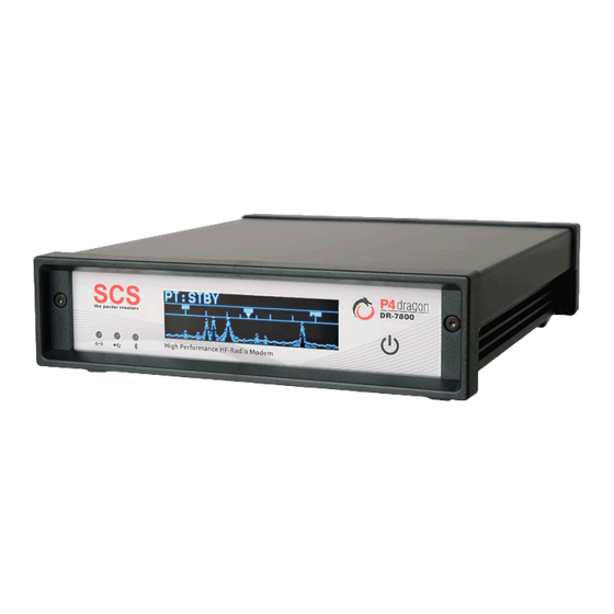
- Page 42 8. Display und LEDs 8 Display und LEDs Abbildung 23: Die P4dragon Frontansicht. Der P4dragon besitzt drei LEDs und ein großes, einfarbiges (blau) OLED-Display. Das OLED-Display Im P4dragon findet ein OLED-Display mit Größe von 256 x 64 Pixel Verwendung. OLED bedeutet “Organic Light Emitting Diode”...
- Page 43 8. Display und LEDs 8.1.1 Inhalte des OLED Displays Das Display kann verschiedene Inhalte bzw. Seiten anzeigen. Die Umschaltung zwischen den Seiten geschieht mit dem Sensorfeld . Wir empfehlen, einfach mal damit zu „spielen“, um sowohl die Inhalte als auch die Reaktion des Sensors zu erkunden. Anzahl und Inhalte werden sich im Laufe der Zeit durch häufige Firmware-Updates ändern.
- Page 44 8. Display und LEDs Die LEDs Der P4dragon hat drei LEDs auf der Frontplatte: Zeigt Bluetooth-Aktivität an. Blinkt langsam wenn die Bluetooth-Option installiert ist und flackert (bzw. leuchtet permanent) bei einem bestehenden Bluetooth-Verbindung zu einem PC Zeigt USB-Aktivität mit einer zweifarbigen LED rot/grün an. Zeigt Aktivität auf dem Ethernet-Netzwerk an wenn die Netzwerk-Option installiert ist.
- Page 45 8. Display und LEDs...
- Page 46 9. Konfigurations-Schalter 9 Konfigurations-Schalter Der P4dragon hat drei DIP-Schalter, um gewisse Dinge zu konfigurieren. Der Konfigurations-Schalter auf der Rückseite Abbildung 28: Konfigurations-Schalter Dieser Schalter hat vier Positionen, mit denen verschiedene Dinge voreingestellt werden können. Alle Schalter können auf ON (untere Position) oder OFF (obere Position) gestellt werden.
- Page 47 9. Konfigurations-Schalter...
- Page 48 10 Zubehör 10 Zubehör Für den SCS P4dragon ist folgendes Zubehör erhältlich: • Bluetooth-Option Hochleistungs-Bluetooth-Einsteckmodul für den DR7800. Bestell-Nr.: TBD • Netzwerk Option (Linux Computer Modul DNP) Befähigt den DR7800 zum Anschluss und Betrieb in einer Ethernet-Netzwerk-Umgebung. Bestell -Nr.: TBD •...
- Page 49 Kabelende ist offen. Jede Ader ist abisoliert und verzinnt. Kabellänge ca. 1,5 Meter. • Kabel mit 5-pol DIN-Stecker Bestell-Nr.: 8010 • Kabel mit 8-pol DIN-Stecker Bestell-Nr.: 8020 • Kabel mit 13-pol DIN-Stecker Bestell-Nr.: 8070 Weiteres Zubehör und Preise entnehmen Sie bitte unserer Internet-Webseite http://www.scs-ptc.com oder fordern Sie unsere aktuelle Preisliste an.
-
Page 50: Technische Daten
11 Technische Daten 11 Technische Daten 15 ΚΩ, symmetrisch/unsymmetrisch, transformatorgekoppelt Audio Eingangsimpedanz: Audio Eingangspegel: 10 mVp-p... 5.5Vp-p 300 Ω, symmetrisch/unsymmetrisch, transformatorgekoppelt Audio Ausgangsimpedanz: Audio Ausgangspegel: Max. 9 Vp-p (unbelastet), einstellbar in 1 mV Schritten Prozessor: Quad StarCore Digital Signal Processor (DSP) 400 MHz, 64 BIT ROM: 2 Mbyte FLASH Speicher, via USB oder Bluetooth updatebar RAM:... - Page 51 11 Technical Data...
- Page 52 Thank you for purchasing the SCS P4dragon DR7800 high performance HF radio modem. SCS modems are the original PACTOR mode modems developed by the people who have created all PACTOR modes. From SCS and SCS representatives, you will receive the best possible support and benefit from the concentrated knowledge of the PACTOR engineers who invented PACTOR.
- Page 53 1. Introduction you on the air. You will find many popular software packages on the SCS CD-ROM supplied with your P4dragon modem. The SCS CD-ROM The SCS CD-ROM contains software to operate the P4dragon in various modes and important hints and information about the operation. Additionally the CD contains the USB driver and a...
- Page 54 SCSmail is freeware and will be distributed via the SCS CD and the SCS website. It runs in an MS Windows (XP or later) environment and can be used as server and as client, which is decided simply with one mouse click in the setup. The main goal with the development of SCSmail was to make it easy to use.
- Page 55 SCSupdate is the recommended one which comes from SCS directly. You can check for new firmware in the download section of the SCS website. If you find a newer version there than actually installed in your modem, you can download the firmware file from there.
- Page 56 The result was a high robustness on weak HF channels. In the year 1995 DSPs became available and this new technology was used by SCS to create PACTOR-2. The waveform became PSK and a very efficient error control coding was added, which significantly increased the speed and robustness.
- Page 57 3. The PACTOR Modes PACTOR-4 (P4) As over the years the computation power of the Digital Signal Processors being available has dramatically increased, it seemed possible also to increase the transfer speed and robustness of PACTOR-3 by at least factor two, while maintaining the bandwidth being occupied. The development of PACTOR-4 begun in the year 2006 on a new DSP chipset from Freescale which was called “StarCore”.
- Page 58 PACTOR-IP-Bridge ( future feature of the DR7800 The PACTOR-IP-Bridge (PIB) is a Network Integration Protocol developed by SCS. The dominant protocols of the Internet like TCP/IP, as well as the Point-to-Point Protocol (PPP), which have become standard for establishment of links between Internet applications, are combined with the PACTOR modes.
- Page 59 3. The PACTOR Modes Summarizing the qualities of the PIB: • TCP/IP-transparent and relatively fast Internet access via HF-radio. • Internet-services accessible via PACTOR, e.g. E-Mail (SMTP/POP3), FTP, HTTP, ... • Up to 4 Internet channels ("sockets") over one physical PACTOR link. •...
- Page 60 PACTOR and the P4dragon automatically by email. Repairs If a problem occurs and it’s necessary to send your SCS product to maintenance, please take care of the following: • Always contact SCS by email before sending a modem. You will be supplied with return instructions which are important for receiving modems from outside the EU.
- Page 61 4. Support...
- Page 62 5. Installation 5 Installation The installation of the P4dragon is simple. You only need to configure the cable between the P4dragon, the computer and the transceiver, if this is not already available. Power supply The P4dragon has three inputs for its power connections which can be used alternatively. Either connect via the DC-in screw terminal socket at the rear of the unit, or via one of the connectors for the short-wave transceiver (MAIN Audio or AUX Audio, pin 5).
- Page 63 “No, not this time” and then click on “Next”. • The wizzard now wants to install the driver for the SCS Radio Modem Device. Select the option “Install the software automatically” and click on “Next”. •...
- Page 64 Bluetooth Sticks of various brands are available from computer stores. The installation should be done in accordance with the instructions of the Bluetooth Stick vendor (driver and software, etc.). SCS does not supply Bluetooth stick software on the SCS-CD. Please use the CD from the Bluetooth Stick manufacturer for the installation!
- Page 65 5. Installation Figure 3: P4dragon with flipped down front panel Now, from the rear side, press a bit on the network cable connector to unlock the main board: Figure 4: Pushing out the mainboard Now the main board can be pulled out of the aluminium housing. The Bluetooth transceiver is to be installed behind the three LEDs on the front side of the modem.
- Page 66 5. Installation Figure 6: Installing the standoffs The bottom side of the Bluetooth transceiver has a connector which mates with the connector on the P4dragon mainboard. Figure 7: The Bluetooth module Align the Bluetooth transceiver on the standoffs so that the mating connectors are close together and matching.
- Page 67 5. Installation Reassembling the P4dragon: After the installation is done the P4dragon mainboard can be fitted again into the housing. While doing this, have a close look to the green “GPS” and “DC-in” connectors and ensure that they slip completely through their holes on the rear panel. Use an appropriate tool (e.g. tweeters) to align them if necessary.
- Page 68 P4dragon and PC really does not matter. Just with timing critical access protocols like hostmode and applications like FAX the response time of the Internet can be the limiting factor. A hostmode connection between two SCS locations inside Germany, however, was no problem.
- Page 69 5. Installation While the P4dragon can be located some distance from the computer, it is still connected to that one computer only, just as a serial-port or USB modem, except being connected via a network. It can also be “disconnected” from one computer and “connected” to another, just like a serial or USB-modem, except this happens by opening and closing TCP/IP network connections.
- Page 70 5. Installation is or changed to another desired value. Data Port is the only configuration necessary at the P4dragon side. It must have the same value as “Port” in the SER2NET setup. See below. Figure 11: Entering the port number Entries in the Settings tab can be left at default.
- Page 71 5. Installation 5.4.4 Using SER2NET After having made the settings described above, simply press the button Create COM . Figure 13: SER2NET configuration You now see the VSP (virtual serial port) Status has switched to Created and the LAN Status has switched to Connected.
- Page 72 5. Installation Figure 14: COM port configuration within SER2NET 5.4.5 Using the SER2NET feature with Airmail Airmail can be used in the manner described above, which means by using the HW-groups SER2NET driver. But Airmail is an intelligent program, it does not need it and with this, Airmail makes it much easier for the user to access the P4dragon and to operate it.
- Page 73 5. Installation Figure 15: SER2NET integrated in Airmail...
- Page 74 6. Connectors 6 Connectors Grounding and Shielding The P4dragon has several connectors where cables can be or must be attached for a proper operation. All this cables should be and are shielded. The shield is usually connected to the shelf of the connector. Each connector of the P4dragon will get in contact with the cable shield and feeds the shield signal to a ground plane on the bottom side of the printed circuit board (PCB).
- Page 75 This is done with internal DIP switches, for both transceiver ports separately. With this switches set to ON the DR7800 is fully connection compatible with all earlier SCS modems, while maintaining the signal isolation. This is how the P4dragon is delivered by default to the customer.
- Page 76 6. Connectors Figure 17: Location of the balanced/unbalanced switches The following schematic shows how the switches work: Figure 18: Function of the balanced/unbalanced switches...
- Page 77 6. Connectors 6.2.2 Connector Pin Description PIN 1: Audio output 1 from the modem to the transmitter. The modem supplies a pure audio signal to the microphone (or ACC) input of the transceiver. The output amplitude can be adjusted with the FSKA and PSKA commands from 30 to 6000 mV (peak to peak) open circuit.
- Page 78 ON! See chapter 6.2.1 for details. Transceiver Remote Control connection The SCS P4dragon is equipped with a connector for controlling many common modern amateur radio transceivers. Virtually all newer transceivers from KENWOOD, ICOM, YAESU, SGC and R&S allow remote controlling of various functions via a serial interface.
- Page 79 6. Connectors The 13 pin DIN Remote-control socket is connected as follows. Seen from the back of the P4dragon: Pin 1: RxD TTL. Pin 2: RTS V24. Pin 3: TXD V24. Pin 4: CTS V24. Pin 5: CTS TTL. Pin 6: ICOM. Pin 7: Not connected.
- Page 80 6. Connectors DC-in This is the main supply power input of the P4dragon. For details refer to chapter 5.1. As the P4dragon is an USB slave device (modem), this “USB type B” connector is used to connect it to a PC. Use the attached USB cable to do so. Refer to chapter 5.2 for details. The P4dragon uses a 3-pole screw terminator to connect to a GPS receiver.
- Page 81 6. Connectors...
- Page 82 7. Connecting to a Transceiver 7 Connecting to a Transceiver Audio connecting 7.1.1 Connection to ICOM Most ICOM transceivers that use 8 pin DIN plug (ACC) can be connected this way: P4dragon Color Signal ICOM 8 pin PIN 2 white PIN 2 PIN 3 yellow...
- Page 83 7. Connecting to a Transceiver 7.1.2 Connection to Kenwood Most Kenwood transceivers that use 13 pin DIN plug (ACC2) can be connected this way: P4dragon Color Signal Kenwood PIN 2 white PIN 4, 8, 12 PIN 3 yellow PIN 9 AF-OUT PIN 1 violet PIN 11...
- Page 84 7. Connecting to a Transceiver - For HF and 1k2 Packet-Radio: P4dragon Color Signal YAESU PIN 2 white PIN 2 PIN 3 yellow PIN 3 AF-OUT PIN 1 violet PIN 1 AF-IN PIN 4 green PIN 5 This cable is available completely assembled. Refer to chapter on page 89.
- Page 85 7. Connecting to a Transceiver Signal P4dragon Color KENWOOD PIN 3 yellow PIN 3 PIN 8 PIN 2 PIN 4 green PIN 8 PIN 2 white PIN 7 PIN 13 orange PIN 5 This cable is available completely assembled. Refer to chapter on page 89.
- Page 86 7. Connecting to a Transceiver Signal P4dragon Color YAESU PIN 3 yellow PIN 3 PIN 8 PIN 2 PIN 13 orange PIN 5 This cable is available completely assembled. Refer to chapter on page 89. Table 17: YAESU V24 Portable transceivers like the FT-100, FT-817, FT-857 or FT-897 use a 8 pin Mini-DIN connection: Signal P4dragon Color...
- Page 87 7. Connecting to a Transceiver Don’t overdrive the TRX because in this case the signal will be spreaded by intermodulation! With proper settings the peak envelope power will nearly be equal to the maximum output power of the TRX. In this case the average power will approximately be the half of the maximum power, so also continuous operation will not cause problems at all.
-
Page 88: Display And Leds
8. Display and LEDs 8 Display and LEDs Figure 24: The P4dragon front view. The P4dragon is equipped with 3 LEDs and a large monochrome (blue) OLED display. The OLED Display The display used in the P4dragon has 256 x 64 pixels. OLED means “Organic Light Emitting Diode”. - Page 89 8. Display and LEDs 8.1.1 Contents of the OLED Display There are several display pages available which can be selected with the sensor. The user is encouraged to just “play” with the sensor and the display contents. The pages count and contents available will vary and extend over the lifetime of the product, as firmware development will continue in a progressive way.
- Page 90 8. Display and LEDs The LEDs The P4dragon has 3 LEDs on the front panel: shows Bluetooth activity with a blue LED flickering, when installed Shows USB activity with a bi-color LED (red/green) Shows activity on the Ethernet network when a DNP is installed Also the LED on the rear side Ethernet connector show activity on the Ethernet network when a DNP is installed.
- Page 91 8. Display and LEDs...
-
Page 92: Configuration Switches
9. Configuration switches 9 Configuration switches The P4dragon has 3 DIP switches to do some basic configuration. Rear side configuration switch Figure 29: Configuration switches This switch has 4 positions with different meanings. All of these can be switched on or off. ON means that the switch is set to the lower position, OFF is the higher position. - Page 93 9. Configuration switches 9.1.3 DHCP switch This switch enables the DHCP function of the network option when installed. DHCP means that the device gets the IP address assigned automatically by the DHCP server (router) in the network. With DHCP off, the IP address can be configured manually. Also refer to chapter 5.4 on this matter.
- Page 94 10 Accessories 10 Accessories For the SCS P4dragon the following accessories are available: • Bluetooth option High power Bluetooth transceiver to plug in the DR7800. Order-No.: TBD • Network Option (Linux Computer Module DNP) Enables the DR7800 to be used and controlled in Ethernet network environment Order-No.: TBD...
- Page 95 • Cable with 5 pin DIN connector Order-No.: 8010 • Cable with 8 pin DIN connector Order-No.: 8020 • Cable with 13 pin DIN connector Order-No.: 8070 For additional accessories and prices please refer to our homapage http://www.scs-ptc.com call for a recent pricelist.
-
Page 96: Technical Data
11 Technical Data 11 Technical Data 15 ΚΩ balanced/unbalanced, transformer coupled Audio input impedance: Audio input level: 10 mVp-p... 5.5Vp-p 300 Ω balanced/unbalanced, transformer coupled Audio output impedance: Audio output level: Max. 9 Vp-p (open circuit), adjustable in 1 mV steps Processing: Quad StarCore Digital Signal Processor (DSP) 400 MHz, 64 BIT ROM:...
Need help?
Do you have a question about the P4dragon DR-7800 and is the answer not in the manual?
Questions and answers