
Related Manuals for Apricus Sentinel S4

Summary of Contents for Apricus Sentinel S4
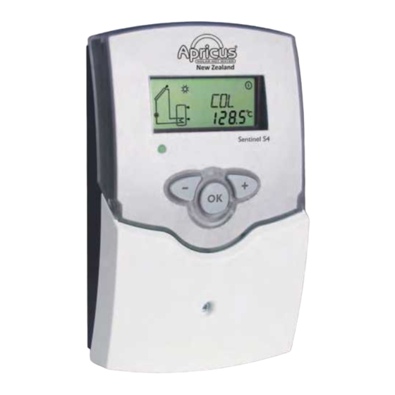
- Page 1 Sentinel S4 (version 2) Mounting Connection Operation Application examples Manual Thanks for buying this product. Read this manual carefully to get the best perfomance from this unit.
-
Page 2: Table Of Contents
Sentinel S4 Contents Overview ..............3 Operation and function ......... 14 Installation ............4 2.1 Push buttons ..............14 1.1 Mounting ................4 2.2 System-Monitoring-Display ...........14 1.2 Electrical connection ............4 2.3 Flashing codes ..............15 Channel overview ........... 16 1.3 Data communication / Bus..........5 1.4 Terminal allocation in the different system layouts ..6... -
Page 3: Overview
Sentinel S4 Overview • System-monitoring-display • Up to 4 Pt1000 temperature sensors • semiconductor relay for pump speed control • 3 basic system layouts to choose from • Heat quantity measurement • VBus ® • Function control • Thermostat function (time-controlled) •... -
Page 4: Installation
Sentinel S4 Installation Mounting WARNING! Electric shock! display Opening the housing will expose live parts! Î Switch off power supply and disconnect the device from po- wer supply before opening the housing! push cover button The unit must only be installed •... -
Page 5: Data Communication / Bus
Sentinel S4 Connecting the device to the mains supply must always be the last step of the installation! The power supply to the controller must be carried out via an external power switch (last step!). The supply voltage must be 100 … 240 V~ (50 … 60 Hz). Flexible cables must be attached to the housing with the enclosed strain relief and the corresponding screws. -
Page 6: Terminal Allocation In The Different System Layouts
Sentinel S4 Terminal allocation in the different system layouts System layout 1 Sensors S3 and S4 can optionally be connected for mea- The controller calculates the temperature difference surement purposes. S3 can optionally be used as reference between collector sensor S1 and store sensor S2. If the sensor for the store emergency shutdown option (OSEM). - Page 7 Sentinel S4 Adjustment Channels Channel Description Factory setting Page System DT O Switch-on temperature difference 8.0 K [16.0 °Ra] DT F Switch-off temperature difference 2.0 K [4.0 °Ra] DT S Nominal temperature difference 10.0 K [20.0 °Ra] Rise control R1 2 K [4 °Ra]...
-
Page 8: System Layout 2
Sentinel S4 System layout 2 The controller calculates the temperature difference the adjusted thermostat switch-on temperature (AH O) is between collector sensor S1 and store sensor S2. If the reached. This function can optionally be combined with up difference is larger than or identical to the adjusted switch- to three adjustable time frames. - Page 9 Sentinel S4 Adjustment Channels Channel Description Factory setting Page System DT O Switch-on temperature difference 8.0 K [16.0 °Ra] DT F Switch-off temperature difference 2.0 K [4.0 °Ra] DT S Nominal temperature difference 10.0 K [20.0 °Ra] Rise control R1 2 K [4 °Ra]...
-
Page 10: System-Specific Functions
Sentinel S4 The following functions are exclusively available in system System-specific functions layout 2. The corresponding channels will not be available in any other system layout. Thermostat function The thermostat function works independently from the Afterheating solar operation and can be used for using surplus energy or for afterheating. - Page 11 Sentinel S4 Option: Thermal disinfection of the upper DHW zone (OTD) This function is used for protecting the upper store zone OTD: against Legionella by activating the afterheating. Thermal disinfection function Reference sensor for the thermal disinfection is S3! Adjustment range: ON / OFF Î...
-
Page 12: System Layout 3
Sentinel S4 System layout 3 The controller calculates the temperature difference valve will be operated by relay 2 in order to direct the between collector sensor S1 and store sensor S2. If the surplus energy to a heat dump. For security purpose this... -
Page 13: Symbol
Sentinel S4 Adjustment Channels Channel Description Factory setting Page System DT O Switch-on temperature difference 8.0 K [16.0 °Ra] DT F Switch-off temperature difference 2.0 K [4.0 °Ra] DT S Nominal temperature difference 10.0 K [20.0 °Ra] Rise control R1 2 K [4 °Ra]... -
Page 14: Operation And Function
Sentinel S4 Operation and function Push buttons The controller is operated via three push buttons below the display. Button 1 is used for scrolling forward through the indica- tion menu or to increase the adjustment values. Button 2 is operating control used for scrolling backward and reducing values. -
Page 15: Flashing Codes
Sentinel S4 System screen The system screen (active system layout) shows the system selected on the controller. It consists of several system component symbols, which are – depending on the current status of the system – either flashing, permanently shown or hidden. -
Page 16: Channel Overview
Sentinel S4 Channel overview Display channels Note: The displayed values and adjustment channels depend on which system layout, which options and functions have been selected. Only values and adjustment channels available for the indi- Indication of drainback time periods vidual settings selected will appear in the menu. - Page 17 Sentinel S4 Indication of current pump speed Indicates the current pump speed of the solar pump. n %: Current pump speed Indicates the energy gained in heat quantity – only available Display range: 30 … 100 % if heat quantity measurement (OHQM) is activated.
-
Page 18: Adjustment Channels
Sentinel S4 Adjustment channels In this channel, a pre-defined system layout can be selected. System layout selection Each system layout has a set of pre-programmed settings Arr: that can be individually changed. System layout selection. If the system layout selection is changed later on, all adjust- Adjustment range: 1 …... - Page 19 Sentinel S4 Minimum pump speed A relative minimum pump speed can be allocated to the output R1 via the adjustment channel nMN. nMN: Pump speed control Note: Adjustment range: 30 … 100 When a load which is not speed-controlled is...
- Page 20 Sentinel S4 Cooling functions In the following the three cooling functions – collector cooling, system cooling and store cooling – are described in detail. The following notes are valid for all three cooling functions: Note: The cooling functions will not become active as long as solar loading is possible.
- Page 21 Sentinel S4 Store cooling function When the store cooling function is activated, the controller aims to cool down the store during the night in order to OSTC: prepare it for solar loading on the following day. Store cooling option Adjustment range: OFF / ON...
- Page 22 Sentinel S4 Tube collector function This function helps overcome the disadvantages caused by O TC: the non-ideal sensor position with some tube collectors. Tube collector function This function operates within an adjusted time frame (be- Adjustment range: OFF / ON ginning at TCST and ending at TCEN).
- Page 23 Sentinel S4 Drainback option A drainback system permits the heat transfer fluid to drain back into the holding tank when solar energy is not col- Note: lected. The drainback option will initiate the filling of the A drainback system layout requires additional system when solar loading begins.
- Page 24 Sentinel S4 Operating mode For control and service work, the operating mode of the controller can be manually adjusted. For this purpose, select MAN1 / MAN2: the adjustment value MAN1, MAN2 in which the following Operating mode adjustments can be made:...
-
Page 25: Troubleshooting
Sentinel S4 Troubleshooting fuse In the case of an error, a message is shown on the display of the controller: 100 ... 240 V~ 50-60 Hz CU 72091163 01 Warning symbols IP 20 1 (1) A 100 ... 240 V~ 1 (1) A 100 ... -
Page 26: Various
Sentinel S4 Various Pump is overheated, but no heat transfer from the collec- Pump starts for a short moment, switches off, switches tor to the store, flow and return have the same tempera- on again, etc. ture; perhaps also air / gas bubbles in the lines. - Page 27 Sentinel S4 Stores cool down at night Control the non-return Fur ther pumps which valve in warm water cir- are connected to the so- culation - o.k. lar store must also be checked. Collector circuit pump Check controller: runs during the night?
-
Page 28: Accessories
Sentinel S4 Accessories Sensors Our product range includes high-precision platinum temperature sensors, flatscrew sensors, outdoor temperature sensors, indoor temperature sensors, cylindrical clip-on sensors, also as complete sensors with immersion sleeve. For more information, see our catalogue and price list. Overvoltage protection device In order to avoid overvoltage damage at collector sensors (e.g. - Page 29 Sentinel S4 DL3 Datalogger Be it solar thermal, heating or DHW heat exchange controllers – with the DL3, you can easily and conveniently log system data of up to 6 controllers. Get a comprehensive over- view of all controllers connected with the large full graphic display. Transfer data with an SD memory card or use the LAN interface to view and process data on your PC.
- Page 30 Sentinel S4 | 30...
- Page 31 Sentinel S4 31 |...
-
Page 32: Impressum
Sentinel S4 Apricus NZ Distributed by: PO Box 317 Whakatane 3158 © All contents of this document are protected by copyright. | 32...
Need help?
Do you have a question about the Sentinel S4 and is the answer not in the manual?
Questions and answers