Table of Contents
Advertisement
Quick Links
Download this manual
See also:
Basic Documentation
Advertisement
Table of Contents

Subscribe to Our Youtube Channel
Related Manuals for Siemens Synco 200


Summary of Contents for Siemens Synco 200
- Page 1 Synco 200 – Commissioning guide Answers for infrastructure.
- Page 2 Summarized, this booklet provides you with all necessary basic information to commis- sion the Synco 200 controllers in an easy, comfortable and efficient way. If you need more detailed information, please refer to the Synco 200 basic documenta- tion (Document No. CE1P3101en) or contact your local Siemens office.
-
Page 3: Table Of Contents
Content Introduction ........... 4 Operating elements and symbols . -
Page 4: Introduction
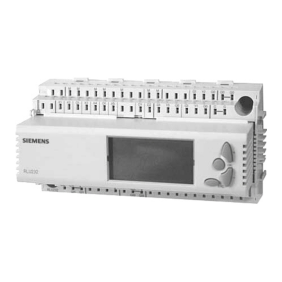
Introduction Operating elements and symbols Operating elements 1 Display 2 Navigation buttons – for selec- D1 D2 X1 X2 X3 X4 SERVICE PASS ting menu lines or adjusting values COMMIS INFO PARA MODE PARA 3 OK button – for confirming menu APPL ID CONF TEST 1 2 3... -
Page 5: List Of Abbreviations
List of abbreviations °C Degrees Celsius HEAT Heating °F Degrees Fahrenheit HREC Mixing damper/Heat recovery %OPEN INFO Information inputs/outputs Outside temp-dependent open IN X Universal 000.0 Preselection external 0000 Universal 0000 INVALID Caution! Invalid settings 0–10 0–10 V INVERS Inversion 2xNI KICK Kick period... - Page 6 D1 D2 X1 X2 X3 X4 SERVICE PASS COMMIS INFO PARA MODE X1 X2 SERVICE PASS D1 D2 X3 X4 PARA PASS Password level SERV Service level COMMIS INFO PARA MODE APPL ID CONF TEST D1 D2 X1 X2 X3 X4 SERVICE PASS 1 2 3...
-
Page 7: Commissioning
Commissioning Access level overview How to get into the different access levels User level Service level Password level Access to info pages and Access to info pages Access to all menus setpoint menu and setting menus Press OK + ESC Press OK + ESC Press OK + ESC Menu overview... -
Page 8: Navigation Overview - User Level
Navigation overview – user level Info pages Info pages show actual values, Setpoint menu SET to define setpoints (see page 18) - Page 9 setpoints, fault messages and other user relevant data (see page 20)
-
Page 10: Navigation Overview - Service Level
Navigation overview – service level Info pages Info pages show actual values, Setting menus INFO shows all inputs and PARA to define parameters outputs (see page 17) (see page 16) - Page 11 setpoints, fault messages and other user relevant data (see page 20) SET to define setpoints (see page 18)
-
Page 12: Navigation Overview - Password Level
Navigation overview – password level Info pages Info pages show actual values, Setting menus INFO shows all inputs and outputs (see page 17) Commissioning menus (see page 16) PARA to define parameters SET to define setpoints... - Page 13 setpoints, fault messages and other user relevant data (see page 20) PARA to define parameters SET to define setpoints (see page 16) (see page 18) APPL ID to choose an CONF to define configu- TEST to check inputs and application ration to simulate outputs...
-
Page 14: Getting Started
Getting started 1 How to get into the pass- 2 How to select a preprogrammed application word protected area (APPL ID) Press OK + ESC Info page in the password level Press OK Press OK Setting menus Press OK Press OK Stop the plant Press OK Commissioning... -
Page 15: How To Start A Standard Application
3 How to start a preprogrammed application Application number Press OK, select number, press OK Warning page Press OK Parameter menu (to define parame- ters see page 16) Press ESC Start the plant Press OK Commissioning menu Press ESC Info page... -
Page 16: How To Adjust Configuration And Settings
4 How to adjust configuration and settings – How to define parameters (PARA), setpoints (SET), applications (APPL ID) – How to adjust a standard application (CONF) – How to test inputs and outputs (TEST) Menus in COMMIS Parameter menu: Press OK Select PARA …to define parameters Select an input or a function... -
Page 17: How To Check Inputs And Outputs (Info)
5 How to check inputs and outputs (INFO) (only in password or service level) This menu allows you to look up all input and output values to check your plant. Info page Press OK Press ESC Select INFO INFO menu Press OK Press ESC Checking outside... -
Page 18: How To Define Setpoints (Set)
6 How to define setpoints (SET) (in all levels) Info page Press OK Commissioning menu Select SET Press OK Setpoint menu Press ESC Press OK Press ESC Setpoints... -
Page 19: How To Protect Your Settings By Selecting The User Level
7 How to protect your settings by selecting the user level Info page in the password level Press OK + ESC Select USER Change to the user level Press OK Info page in the user level... -
Page 20: Info Pages Overview
Info pages overview Number and content of the info pages depend on the loaded application User level Service and Description password level Shows actual room temperature and setpoint Shows actual supply air tempe- rature and calculated setpoint or temperature limits Shows all configured sequen- ces. -
Page 21: Preprogrammed Applications
Preprogrammed Applications Air handling applications Air pressure and air quality control ∆p N.X1 [ppm] N.Q2 N.X3 N.Y2 N.Y1 ∆p N.X4 N.Q1 N.Q1 N.X1 N.X3 N.X5 N.Q2 N.Y1 R5.1 R5.2 N.X4 N.X2 N.D1 N.D1 N.X2 RLU222 APPL ID: U06 RLU232 APPL ID: U02 N.X1 [ppm] N.X1... -
Page 22: Temperature Control: Cooling Coil
Temperature control: Cooling coil N.X2 Cascade N.X1 N.X4 N.X4 N.X3 N.X2 N.X1 N.X3 N.Q1 N.Q2 N.Y1 N.D1 N.D1 RLU220 APPL ID: A06 RLU202 APPL ID: A05 N.X2 Cascade N.X1 N.X4 N.X4 N.X2 N.X3 N.Y2 N.X3 N.X1 N.D1 N.Q1 N.Q2 N.D1 N.Y1 RLU220 APPL ID: A07... -
Page 23: Temperature Control: Heating Coil, Water
Temperature control: Heating coil, water (1) N.X2 Cascade N.X1 N.X4 N.X4 N.X3 N.X1 N.X3 N.X2 N.Q1 N.Q2 N.D1 N.D1 N.Y1 RLU202 APPL ID: A03 RLU220 APPL ID: A01 N.Q1 N.X1 N.X1 N.X3 N.X3 N.X4 N.X2 N.X4 N.X2 N.Q2 N.Y1 N.D1 N.Y1 N.D1 RLU222... -
Page 24: Temperature Control: Heating Coil, Electric
Temperature control: Heating coil, water (2) M3.1 B1.1 M3.2 B1.2 N.X1 N.X3 N.Q1 N.Q3 R5.1 R5.2 N.X2 N.X4 Y3.1 Y3.2 N.Y1 N.Y2 N.X5 N.D1 RLU232 APPL ID: U01 Temperature control: Heating coil, electric N.X2 Cascade N.X1 N.X4 N.X4 N.Q4 N.Q5 N.Q1 N.X3 N.Q1... -
Page 25: Temperature Control: Heating + Cooling Coil, Water (1)
Temperature control: Heating + cooling coil, water (1) N.X1 N.X3 N.X2 N.X4 N.X1 N.Y1 N.Y2 N.X2 N.D1 N.D1 N.Y1 RLU220 APPL ID: A09 RLU220 APPL ID: U10 N.X1 N.X1 N.X4 N.X2 N.X3 N.X2 N.Y1 N.Y2 N.D1 N.Y1 N.Y2 N.D1 RLU220 APPL ID: A10 RLU222 APPL ID: U13... -
Page 26: Temperature Control: Heating + Cooling Coil, Water (2)
Temperature control: Heating + cooling coil, water (2) N.Q1 N.X2 Cascade N.X1 N.X3 N.X4 N.X3 N.X1 N.X2 N.X4 N.Q1 N.Q2 N.Q3 N.D1 N.D1 N.Y1 N.Y2 N.Y1 N.Y2 N.D2 RLU222 APPL ID: A09 RLU232 APPL ID: A03 N.X2 N.X2 Cascade Cascade N.X4 N.X4 N.X1... -
Page 27: Temperature Control: Heating + Cooling Coil, Dx Cooler
Temperature control: Heating + cooling coil, DX cooler N.Q1 N.X1 N.X1 N.X3 N.X5 N.X4 N.X2 N.X4 N.Y2 N.X2 N.Q2 N.X3 N.Y2 N.D1 N.Q3 N.Y1 N.D2 N.Q4 N.Q1 N.Y1 N.D1 N.Q5 N.Q2 N.Q6 RLU236 APPL ID: A07 RLU222 APPL ID: A13 N.Q1 N.X2 N.X2... -
Page 28: Temperature Control: Heating + Cooling Coil, Electric Heater
Temperature control: Heating + cooling coil, electric heater N.X1 N.X4 N.Q1 N.X2 N.X3 N.Q2 N.Y1 N.D1 N.Y2 RLU222 APPL ID: A11 N.X2 Cascade N.X4 N.Q1 N.X1 N.X3 N.Q2 N.Y1 N.Y2 N.D1 RLU222 APPL ID: A12 N.X1 N.X4 N.X2 N.X3 N.Q1 N.Y2 N.Q2 N.Q3... -
Page 29: Temperature Control: Heating + Cooling Coil + Mixing Dampers
Temperature control: Heating + cooling coil + mixing dampers N.X2 Cascade N.X1 N.Y2 N.Y1 N.X4 N.X4 N.Q1 N.X1 N.X3 N.X3 N.X2 N.Q2 N.Q1 N.Q2 N.D1 N.D1 N.Y1 N.Y2 RLU222 APPL ID: A24 RLU222 APPL ID: A29 N.X2 Cascade N.X1 N.Y1 N.Y2 N.X4 N.X4... -
Page 30: Temperature Control: Heating + Cooling Coil + Heat Recovery
Temperature control: Heating + cooling coil + heat recovery N.Q1 N.X2 Cascade N.X1 N.X4 N.X5 N.X3 N.X5 N.X3 N.X2 N.X1 N.X4 N.Y2 N.Q1 N.Q3 N.Q3 N.Y2 N.D1 N.D1 N.D2 N.Y1 N.Y3 N.Y1 N.Y3 N.D2 RLU232 APPL ID: A06 RLU232 APPL ID: A09 N.Q1 N.Q3 N.X1... -
Page 31: Temperature Control: Heating Coil + Mixing Dampers/Heat Recovery
Temperature control: Heating coil + mixing dampers/heat recovery N.Q1 N.X2 Cascade N.X1 N.Y2 N.X3 N.X4 N.X4 N.X2 N.X1 N.X3 N.Y2 N.Q2 N.D1 N.Y1 N.D1 N.Y1 RLU222 APPL ID: A21 RLU220 APPL ID: A15 N.Q1 N.Q1 N.X2 Cascade N.X4 N.X1 N.Y2 N.X3 N.X3 N.X4... -
Page 32: Humidity Control: Dehumidifier
Humidity control: Dehumidifier φ N.X3 T φ N.X1 N.X1 [g/kg] N.X4 N.X3 N.Y1 N.D1 N.X2 N.Q1 N.D1 N.X2 N.Y1 N.Q2 RLU220 APPL ID: U02 RLU222 APPL ID: U05 φ N.X3 T φ N.X1 N.X1 [g/kg] N.X4 N.X3 N.Y1 N.X2 N.D1 N.Q2 N.Q3 N.Q1... -
Page 33: Humidity Control: Humidifier
Humidity control: Humidifier φ φ N.X1 N.X1 φ φ N.X4 N.X3 N.X2 N.X2 N.Y2 N.Y1 N.Y1 N.Q1 N.D1 N.X3 N.Q2 N.D1 RLU220 APPL ID: U01 RLU222 APPL ID: U07 φ φ N.X1 N.X1 φ N.X4 φ N.X3 N.X2 N.Y2 N.Y1 N.X2 N.Y1 N.D1... -
Page 34: Temperature And Humidity Control: Heating + Cooling Coil + Mixing Dampers/Heat Recovery + Humidifier
Temperature and humidity control: Heating + cooling coil + mixing dampers/heat recovery + humidifier T φ N.X3 N.X2 Cascade φ N.X5 N.X1 N.X4 N.Y3 N.Q1 N.Y2 N.D1 N.Q3 N.Y1 N.D2 RLU232 APPL ID: A12 N.Q1 T φ N.X4 N.X2 Cascade N.Y2 N.X3 N.X5... -
Page 35: Applications For Asian And American Regions
Applications for Asian and American regions N.X1 ∆p N.X3 ∆p N.X4 N.Y1 N.X5 N.X2 N.D1 N.Y2 N.Y3 N.Y1 N.D1 N.Q1 N.D2 N.X1 RLU222 APPL ID: U16 RLU232 APPL ID: A17 ∆p N.Y1 N.X1 N.X5 N.X1 N.D1 ∆p N.D2 N.D1 N.Y1 N.Q3 N.Q1 N.X3... -
Page 36: Heating/Cooling Applications
Heating/Cooling applications Temperature and differential temperature control N.X3 N.X1 N.D1 N.Q1 N.Q2 N.Q2 φ N.X2 N.X1 N.Y1 N.X4 N.X2 N.Q1 N.D1 RLU222 APPL ID: U08 RLU202 APPL ID: U06 N.Q1 N.D1 N.Q2 φ N.X2 N.X1 N.Y1 N.X2 N.X1 N.D1 RLU220 APPL ID: U09 RLU202 APPL ID: U07... -
Page 37: Differential Pressure Control, Liquid
Differential pressure control, liquid p p N.X2 N.X1 N.Q1 N.X1 [bar] N.Q2 N.X3 N.Q3 N.Q4 N.X4 N.Y1 N.D1 N.D1 RLU236 APPL ID: U18 RLU220 APPL ID: U04 ∆p ∆p N.X2 N.X1 [bar] N.Q1 N.Q2 N.Y1 N.Y2 N.X4 N.X3 N.D1 RLU222 APPL ID: U02 ∆p ∆p... -
Page 38: Special Applications
Special applications DC 0 ... 10 V DC 0 ... 10 V X1 M D1 M X1 M D1 M RLU232 RLU202 2Q BIN. RLU202 APPL ID: U10 RLU232 APPL ID: U04 DC 0 ... 10 V DC 0 ... 10 V X1 M D1 M X1 M... - Page 39 DC 0 ... 10 V DC 0 ... 10 V X1 M G1 X1 M G1 RLU236 RLU236 5Q LIN. 5Q VAR. RLU236 APPL ID: U10 RLU236 APPL ID: U14 DC 0 ... 10 V DC 0 ... 10 V X1 M G1 X1 M G1 RLU236...
-
Page 40: Configuration Diagrams
Configuration diagrams RLU202 only in basic type A only in basic type U Type A Type U LABEL LABEL LABEL LABEL SEQLIM CAS/CON SHIFT SEQLIM CTLOOP 1 CTLOOP 1 FROST Type A Type U MODE LABEL LABEL LABEL LABEL y p y p y p y p y p y p y p y p... - Page 41 RLU220 only in basic type A only in basic type U Type A Type U LABEL LABEL LABEL LABEL SEQLIM CAS/CON SHIFT SEQLIM Type A Type U FROST CTLOOP 1 CTLOOP 1 MODE LABEL LABEL LABEL LABEL y1 y2 y1 y2 y1 y2 SEQLIM CAS/CON...
- Page 42 RLU222 only in basic type A only in basic type U Type A Type U LABEL LABEL LABEL LABEL SEQLIM CAS/CON SHIFT SEQLIM SHIFT SEQLIM Type A Type U FROST CTLOOP 1 CTLOOP 1 CTLOOP 2 MODE LABEL LABEL LABEL LABEL y p y p y p y p...
- Page 43 RLU232 only in basic type A only in basic type U Type A Type U LABEL LABEL LABEL LABEL LABEL SEQLIM CAS/CON SHIFT SHIFT SEQLIM SEQLIM Type A Type U FROST CTLOOP 1 CTLOOP 2 CTLOOP 1 MODE LABEL LABEL LABEL LABEL LABEL...
- Page 44 RLU236 only in basic type A only in basic type U Type A Type U LABEL LABEL LABEL LABEL LABEL SEQLIM CAS/CON SHIFT SEQLIM SHIFT SEQLIM FROST CTLOOP 1 Type A Type U CTLOOP 2 CTLOOP 1 MODE LABEL LABEL LABEL LABEL LABEL...
- Page 45 Notes...
- Page 46 Notes...
- Page 48 The required features should therefore be specified in each individual case at the time of closing the contract. Subject to change • Order no. 0-92160-en • © Siemens Switzerland Ltd • Printed in Switzerland • 10810 Ah www.siemens.com www.siemens.com/buildingtechnologies...
Need help?
Do you have a question about the Synco 200 and is the answer not in the manual?
Questions and answers