
Related Manuals for Baltimore Aircoil Company S1500E

Summary of Contents for Baltimore Aircoil Company S1500E
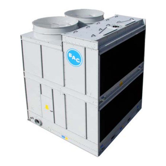
- Page 1 R ACC S1500E v00 EN Options & accessories Open cooling towers S1500E INSTALLATION INSTRUCTIONS...
- Page 2 Notes W W W . B A L T I M O R E A I R C O I L . E U...
-
Page 3: Table Of Contents
Table of contents Page Safety precautions Bottom water outlet / Equalizer / Remote Sump Internal sliding service platform Access to fill pack Internal service platform Internal ladder only External ladder and railing on top of hot water basin Ladder 10 Handrail Discharge attenuation 10 Single discharge atttenuation Double discharge attenuation Intake attenuation... -
Page 4: Safety Precautions
Safety Precautions All electrical, mechanical and rotating machinery constitute a potential hazard, particularly for those not familiar with its design, construction and operation. Accordingly, adequate safeguards (including use of protective enclosures where necessary) should be taken with this equipment both to safeguard the public (including minors) from injury and to prevent damage to the equipment, its associated system and the premises. If there is doubt about safe and proper rigging, installation, operation or maintenance procedures, contact the equipment manufacturer or his representative for advice. When working on operating equipment, be aware that some parts may have an elevated temperature. Any operations on elevated level have to be executed with extra care to prevent accidents. AUTHORIZED PERSONNEL The operation, maintenance and repair of this equipment should be undertaken only by personnel authorized and qualified to do so. All such personnel should be thoroughly familiar with the equipment, the associated systems and controls and the procedures set forth in this and other relevant manuals. Proper care, procedures and tools must be used in handling, lifting, installing, operating and repairing this equipment to prevent personal injury and/or property damage. MECHANICAL SAFETY Mechanical safety of the equipment is in accordance with the requirements of the EU machinery directive. Depending upon site conditions it also may be necessary to install items such as bottom screens, ladders, safety cages, stairways, access platforms, handrails and toe boards for the safety and convenience of the authorized service and maintenance personnel. At no time this equipment should be operated without all fan screens, access panels and access doors in place. When the equipment is operated with a variable fan speed control device, steps must be taken to avoid operating at or near to the fan’s «critical speed». For more information consult your local BAC Balticare representative. (www. baltimoreaircoil.eu) ELECTRICAL SAFETY Each fan and pump motor associated with this equipment should be installed with a lockable disconnect switch located within sight of the equipment. No service work should be performed on or near the fans, motor, drives or inside the equipment unless fan and pump motors, heaters etc. are electrically isolated. LIFTING CAUTION FAILURE TO USE DESIGNATED LIFTING POINTS CAN RESULT IN A DROPPED LOAD CAUSING SEVERE INJURY, DEATH AND/ OR PROPERTY DAMAGE. LIFTS MUST BE PERFORMED BY QUALIFIED RIGGERS FOLLOWING BAC PUBLISHED RIGGING INSTRUCTIONS AND GENERALLY ACCEPTED LIFTING PRACTICES. THE USE OF SUPPLEMENTAL SAFETY SLINGS MAY ALSO BE REQUIRED IF THE LIFT CIRCUMSTANCES WARRANT ITS USE, AS DETERMINED BY THE RIGGING CONTRACTOR. LOCATION All cooling equipment should be located as far away as possible from occupied areas, open windows or air intakes to buildings. CAUTION EACH UNIT SHOULD BE LOCATED AND POSITIONED TO PREVENT THE INTRODUCTION OF DISCHARGE AIR INTO THE VENTILATION SYSTEMS OF THE BUILDING ON WHICH THE UNIT IS LOCATED OR THOSE OF ADJACENT BUILDINGS. For detailed recommendations on BAC equipment layout, please see the BAC Application Handbook EUEdition, the BAC website: www.baltimoreaircoil.eu or contact your local BAC-Balticare Representative. -
Page 5: Bottom Water Outlet / Equalizer / Remote Sump
Bottom water outlet / Equalizer / Remote sump The bottom connection installation, is typical for all bottom outlets, equalizer and remote sump connections. Bottom connection parts are shipped loose. Back-up plate is factory installed Align rubber gasket and bottom connection. Install M8 hardware Internal sliding service platform The sliding platform base and platform ladder is factory installed. The handrail system requires field installation. The handrail vertical posts drop into pre-installed brackets in a specific configuration depending on the size of the unit. Pre-installed platform base and ladder W W W . B A L T I M O R E A I R C O I L . E U... - Page 6 Drop handrail vertical posts into the pre-installed brackets Handrail configuration depending on unit size Slide in the horizontal tubes into the vertical posts, secure with hardware installed in vertical post Secure the vertical posts in each bracket using M12 bolts provided. Gate is pre-welded to one of the vertical posts. W W W . B A L T I M O R E A I R C O I L . E U...
-
Page 7: Access To Fill Pack
Access to fill pack The Internal Sliding Platform can be used to access the fill pack, follow the next steps to move the sliding platform to the fill side. Remove the access ladder by removing the two M12 Remove the M10 securing hardware on each side of the bolts. platform. Remove the handrail and vertical posts. Slide the platform to the fill side and secure again with M10 harware. Assemble access ladder with two M12 bolts. Install the vertical posts and handrail. Now the platform can be used to access the fill pack. W W W . B A L T I M O R E A I R C O I L . E U... -
Page 8: Internal Service Platform
Internal service platform (full area) (only for S15E xxxx-11xE and S15E xxxx-12xE units The Internal Service Platform (full area) and access ladder is factory installed, no field installation is required. The platform can be accessed by opening the sliding grid. Push upwards on one side of the grid to Slide the grid sideways. Make sure the grid is secured by sliding it open to the end position (lock in place). Caution Always close the sliding grid when standing on the platform. Internal ladder only Depending on model the internal ladder is supplied in two parts. Only in this case, slide the two half ladders into the pre-installed U-channels. Install bolts M10 Lift the ladder into place and drop the pre-welded bolts into the mounting holes in the upper support channel. No further fastening is required. Note: The ladder can also be oriented towards the fill pack (similar procedure). -
Page 9: External Ladder And Railing On Top Of Hot Water Basin
External ladder and railing on top of hot water basin The external service ladder, cage and the handrail are shipped loose. Unit with installed ladder and railing Ladder External ladder brackets are factory installed. Lift the ladder and cage into place. BOTTOM MIDDLE Fasten ladder brackets with M12 hardware. W W W . B A L T I M O R E A I R C O I L . E U... -
Page 10: Handrail
Handrail All channels and brackets are factory installed. Install all vertical posts. Slide in handrails and tighten with set screws. Tighten with M10 hardware Discharge attenuation Single discharge attenuation Align the 4 L-brackets with pre-installed Fasten with M10 hardware. Lift single discharge attenuator onto the plates. pre-installed fan cowls. W W W . B A L T I M O R E A I R C O I L . E U... -
Page 11: Double Discharge Attenuation
Double discharge attenuation Align the 4 L-brackets with pre-installed Fasten with M10 hardware. Lift double discharge attenuator onto plates. the pre-installed fan cowls. Intake attenuation Single stack unit Lift the intake attenuator onto the steel or concrete support structure. The shipping strap diagonals can be removed after Make sure the intake attenuator attachment holes line up with the unit holes. Secure with tappers. installation W W W . B A L T I M O R E A I R C O I L . E U... -
Page 12: Double Stack Unit
Double stack unit Lift the lower intake attenuator onto the steel or concrete support structure. Make sure Secure with tappers. the intake attenuator attachment holes line up with the unit holes. Lift the upper intake attenuator onto the Secure with tappers. The shipping strap diagonals can be lower intake attenuator. Make sure the removed after installation intake attenuator attachment holes line up with the unit holes. Note: for model S15E xx18-xxE, the intake attenuator consists of two sections for a single stack unit and four sections for a double stack unit. These sections need to be fastened in the middle pre-installed channels at air intake. W W W . B A L T I M O R E A I R C O I L . E U... -
Page 13: Motor Davit
Motor davit Motor davit support brackets are pre-installed in the Install one bolt & nut facing up on door side of the socket. factory. The davit socket is shipped loose. Attach the davit socket at each motor location. The hook plate is provided to support weight of socket Hook onto bottom flange of fan deck and secure socket to during installation only. pre-installed brackets on unit. Fasten davit socket with M10 hardware to preinstalled Slide in davit arm. brackets. W W W . B A L T I M O R E A I R C O I L . E U... -
Page 14: Shipped Loose Fan Cowl
Shipped loose fan cowl (only on single stack units with WQ fan) Lift a single fan cowl with fan guard onto the two factory installed fan cowls. Each fan Align the hole pattern and tighten with should have stack op 3 cowls on top of each other. tappers W W W . B A L T I M O R E A I R C O I L . E U... -
Page 15: Further Assistance And Information
Further assistance & information BALTICARE BAC has established a specialized independent total care company called Balticare. The BAC Balticare offering involves all elements required to ensure a safe and efficient operation of your evaporative cooling products. From a full range of risk assessment to selective water treatment, training, testing, record keeping and annual system overview. For more details, contact BAC Balticare at www.balticare. com or you can also contact your local BAC representative for further information and specific assistance at www.BaltimoreAircoil.eu. MORE INFORMATION REFERENCE LITERATURE • Eurovent 9-5 (6) Recommended Code of Practice to keep your Cooling System efficient and safe Eurovent/Cecomaf, 2002, 30p. • Guide des Bonnes Pratiques, Legionella et Tours Aéroréfrigérantes. Ministères de l’Emploi et de la Solidarité, Ministère de l’Economie des Finances et de l’Industrie, Ministère de l’Environnement, Juin 2001, 54p. • Voorkom Legionellose. Minsterie van de Vlaamse Gemeenschap. December 2002, 77p. • Legionnaires’ Disease. The Control of Legionella Bacteria in Water Systems. Health & Safety Commission. 2000, 62p. • Hygienische Anforderungen an raumlufttechnische Anlagen. VDI 6022. INTERESTING WEB SITES www.BaltimoreAircoil.eu; www.Balticare.com; www.eurovent-certification.com; www.ewgli.org; www.ashrae.org; www.uniclima.org; www.aicvf.org; www.hse.gov.uk W W W . - Page 16 COOLING TOWERS CLOSED CIRCUIT COOLING TOWERS ICE THERMAL STORAGE EVAPORATIVE CONDENSERS HYBRID PRODUCTS PARTS & SERVICES w w w. B a l t i m o r e A i r c o i l . e u i n f o @ B a l t i m o r e A i r c o i l . e u w w w.
Need help?
Do you have a question about the S1500E and is the answer not in the manual?
Questions and answers