Advertisement
Dear Kickbike - owner,
Thank you for having chosen the Kickbike - scooter! It is our own original
Finnish design, invention and a brand name since 1994. We still have a passion
to develop better products for scooter lovers so the work goes on.
Please read this manual so that you can enjoy your Kickbike without problems.
In the manual there are step by step instructions of how to first assemble your
Kickbike and also how to adjust it to fit your needs. This manual covers all
models. If there are differences in some components it is clearly shown which
model we talk about.
If you have anything to ask please contact your dealer or us directly. It is our
priority that you are happy with the Kickbike - scooter!
Happy kicking!
Hannu Vierikko
"Mr Kickbike"
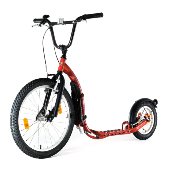
City G4 (Quite similar to Freeride, Sport G4, Cruise MAX 20, Race MAX 20/28)
Cross MAX 20D/20HD (Quite similar to Cross MAX 20V, Cross 29er, FAT MAX)
The frame number is written on the front part of the head tube, just below the Kickbike figure. We recommended you write it here.
My Kickbike frame number is: ___________________________________________________
Contents
➢ Installation and adjustment:
➢ handlebars
➢ mudguards
➢ wheels
➢ tires
➢ brakes
➢ footboard/frame
➢ kickstand
➢ basket
➢ Others:
Part list
A.
Bell
B.
Handlebars
C.
Brake lever
D.
Handlebar stem
E.
Headset bearing
F.
Basket (only in City G4)
G.
Head tube
H. Front brake
I.
Mudguard
J.
Frame
K.
Drinking bottle fixing screws
L.
Footboard
M. Heel stopper
N. Rear brake
O. Quick release skewer
P.
Hub
Q. Rear reflector
R.
Spoke
S.
Rim
T.
Tyre
U.
Valve
V.
Kickstand
W. Remote lockout
X.
Brake disc
Y.
(Suspension) fork
Z.
Brake cables
2
3
4
4
5
6
7
7
7
8
9
9
9
9
Kickbike owner's manual - 1
Advertisement
Table of Contents

Related Manuals for Kickbike Freeride

Summary of Contents for Kickbike Freeride
-
Page 1: Table Of Contents
Handlebars Brake lever Handlebar stem Headset bearing Basket (only in City G4) Head tube H. Front brake Mudguard Frame Drinking bottle fixing screws Footboard M. Heel stopper N. Rear brake O. Quick release skewer Hub Q. Rear reflector City G4 (Quite similar to Freeride, Sport G4, Cruise MAX 20, Race MAX 20/28) Spoke Rim Tyre Valve Kickstand W. Remote lockout Brake disc (Suspension) fork Brake cables Cross MAX 20D/20HD (Quite similar to Cross MAX 20V, Cross 29er, FAT MAX) The frame number is written on the front part of the head tube, just below the Kickbike figure. We recommended you write it here. My Kickbike frame number is: ___________________________________________________ Kickbike owner’s manual - 1 ... - Page 2 Handlebar installation Freeride ( Fig. 1), C ity G4 (Fig. 2) Insert stem into head tube. Tighten stem bolt with a 6mm allen key. (Freeride Fig. 1.2, City Fig. 2) Tighten clamp bolts. (1.2) If you want you can first adjust the angle of the handlebars (Freeride) Notice that the “min insertion” mark has to be inside the head tube! Sport G4, Cross-models, FAT MAX, Cruise MAX 20, Race-models, (Fig. 3) Attach handlebar to stem. (3.1) Tighten bolts Loosen cap bolt. Take care that the front fork doesn’t fall! Lift cap bolt and cap (3.2 - A) Place stem, stem bolt and cap (A) to steerer tube of front fork (3.3) Tighten cap bolt. Finger tightness is enough. Make sure that the stem is straight relative to the front wheel. Tighten clamp bolts. (3.3) Kickbike owner’s manual - 2 ...
-
Page 3: Mudguards
Front mudguard City G4, Sport G4, FAT MAX (Fig. 4) Open the mudguard attachment nut in the fork and place the mudguard Tighten the nut (Use 5mm allen key to prevent bolt from turning). (4.1) Attach the mudguard brackets on both sides of the fork with screws provided. CliX, Cross, Freeride, Race: A plastic frame mudguard is assembled. Check that the fixing straps are tight. (Fig. 5, A) Rear mudguard CliX, City G4, Sport G4, Freeride ( Fig. 6, position B, D) Cross ( Fig. 6, position B, C) Race MAX 20 ( Fig. 6, position A, D) Cruise MAX, FAT MAX (Fig. 6, position A, C) Attach the front part of the mudguard to the rear arch of the footboard. (Fig. 6.1) Attach the mudguard brackets to both sides of the rear fork with screws provided. (Fig. 6) Race MAX 28 no mudguards as standard (optional, Fig. 6, position C, A). ... -
Page 4: Wheels
Installation of the wheels CliX, Freeride, City G4, Sport G4, Cruise MAX, Cross MAX 20V, Race MAX 20 ( Fig. 7 and 8) Race MAX 28 (Fig. 8, skip steps 1,2 by opening switch Fig. 11 A) Cross MAX 20D, Cross MAX 20HD, Cross 29er (Fig. 8, skip steps 1,2 by taking away plastic disc cover Fig. 7.2) note: Quick release skewers are of different lengths in all models except CliX, FAT MAX and Race MAX 28. The longer skewer is for the front wheel. note: Wheels are different sizes in all models except CliX and Race MAX 28. Bigger wheel is the front wheel. To open the brake, squeeze the brake arms… (Fig. 7) ...and slide the brake cable out of it’s slot. (Fig. 7.1) Place the wheel Front wheel (Fig. 8.1) Rear wheel (Fig. 8.2) C liX, City G4, Sport G4, Cross-models, Freeride, FAT MAX ( position B) Race-models, Cruise MAX ( position A) Insert the quick release skewer. Note the position and direction of the springs. (Fig. 8) Tighten the nut of the quick release. (Fig. 8) Close the lever of the quick release. (Fig. 8) At correct tightness you need brisk force but never tools to close it. Align the lever so that it’s not likely to catch your shoelaces. Squeeze both brake arms… (Fig. 8) … to place brake cable back to it’s slot. (Fig. 8.3) ... -
Page 5: Brakes
Adjustment of the brakes V-brakes / Caliper-brakes Freeride, City G4, CliX, Sport G4, Cruise MAX 20, Cross MAX 20V, Race MAX 20 ( Fig. 10) Race MAX 28 ( Fig. 11, skip step 1 by checking that switch (A) is closed +) Use bolt (A) to roughly adjust brake clearance if needed. Use bolts (B) to align brake pads (E) with rims (D). Squeeze brake levers to verify that brake pads (E) contact the rims (D) correctly (see Fig. 10.1). Use screws (C) to center the brake (equalize the clearance from rim to both brake pads). In model R ace MAX 28 c enter the brake by moving whole brake frame by hand. If you have small hands, use adjustment screw (Fig. 12 - A) to get brake levers closer to the handlebar. Use fine adjustment screw (Fig. 12 - B, Fig 11 - F) to get brake pads closer to rims if needed. Test that the brakes work. ... - Page 6 Footboard height adjustment All Kickbike models have an option to choose low or high ride position. Low position (Fig. 14 A) is easier to kick as in the high position (Fig. 14 B) the frame has more ground clearance for safety. C hanging footboard height requires some adjustments! Follow instructions at this page to change the position. Default position in models R ace, Cruise is low (A) and in C ross, Sport G4, City G4, CliX, Freeride, FAT MAX h igh (B) note: Clix will stand upright in folded state only when footboard is in high position. Changing the footboard height Remove the rear wheel (inverse phases page 4) Change the rear mudguard position if needed. High position (Fig. 6, position B) and low position (Fig. 6, position A) In models C ross MAX 20D, Cross MAX 20HD, Cross 29er, FAT MAX adjust the position of the rear brake 3.1. Choose high (Fig. 16 - F) or low position (Fig. 15 - E) adapter according to your setting and attach it to the frame (G) with screws (H) 3.2.
-
Page 7: Suspension Fork
Kickstand adjustment Freeride, City G4, Sport G4, Cross-models, FAT MAX, Cruise MAX 20 ( Fig. 17) Loosen the adjustment screw Adjust the height of kickstand Tighten the adjustment screw Basket installation City G4 ( Fig. 18) Place basket into it’s place Tighten the bolts of frame mount (18.1) Tighten the bolts of fork bracket (18.2) Suspension fork Cross MAX 20V , C ross MAX 20D, Cross MAX 20HD ( Fig. 19) You can lock the suspension fork if needed. C ross MAX 20V l ock suspension from switch (Fig. 19, A) and C ross MAX 20D, Cross MAX 20HD from remote switch (Fig. 19.1, A) in handlebar. ... -
Page 8: Fold & Unfold Clix
Fold & unfold CliX CliX folds in two steps. First fold the frame (fig. 17) Loosen the safety screw (fig. 17 screw 1) Open the CliX frame joint latch. This can be operated with foot (handy if it’s dirty or wet) Fold the frame. Then fold the handlebars (fig. 18). Push up the lock button (fig. 18.1 button 1) Open the latch all the way down (fig. 18.1 latch 2) Fold down the handlebars Carry CliX using the handle at the front of the frame. Handle is balanced so that CliX will stay folded by gravity without any locking mechanisms. This makes folding and unfolding as easy as possible. To unfold CliX, reverse these steps. Unfold the handlebars. Ensure that the quick release (fig. 18.1 latch 2) is fully closed. You should hear a ‘click’ when it locks. Then unfold the frame (fig. 17) and close the CliX frame joint latch. Although CliX is rideable with the safety screw loose (fig. 17.1 screw 1), we recommend tightening it for your safety. Always check that all joints are solidly locked before riding CliX. CliXstand You can lean the CliX on a wall, fence, tree etc. when you lock the head set by turning the CliXstand ring counterclockwise to locked position (Fig. 19). Kickbike owner’s manual - 8 ... -
Page 9: Maintenance
Maintenance Even though the Kickbike is mostly a maintenance free transportation, it is recommended to perform a thorough inspection for loose bolts and spokes after first few hours of riding and also check the tire pressures and tightness of the screws and bolts of your Kickbike once in awhile. Also make sure that all the parts are in good condition. We recommend to take your Kickbike at least once in a year to an expert to get maintained. Warnings Shoelaces We recommend that you tie the shoelaces short and tuck the ends under laces to prevent them from catching brakes, quick release levers or other Kickbike parts while kicking. Curbs The Kickbike footboard is low because it makes kicking easier. It will touch high curbs and speed bumps. Ride safe and slow initially, to get familiar to what kind of obstacles are rideable. If you are not sure whether the footboard will clear a bump, walk it over. Helmet R emember to always use a helmet that fits you well and is an approved bicycle safety helmet. Keep hands in handlebar Do not attempt to ride one handed. Use your leg instead if you need to signal a turn. Warranty We want to make sure that you are happy with our product. The Kickbike Worldwide warranty is 2 years for the frame and one year for other parts. Warranty does not include the normal wear and tear of brake pads, brake cables and tyres. The warranty does not cover problems, which are caused by the lack of maintenance by the user, improper usage of other than standard spare parts for the Kickbike, incorrect methods of maintenance or damages which are caused by normal usage of the Kickbike. The warranty does not cover small unnecessary damages where the strength and usefulness of the Kickbike is not affected. These damages include such as slight uneven paint/varnish/chrome coverage that are caused by the changing weather or/and the normal usage of the Kickbike. The warranty does not cover damages that have been caused by improper usage of the Kickbike, like jumping. Tips Take long “kicks” and enjoy smooth rolling of the Kickbike. It is important to straighten and relax the standing leg after every kick. Switch the kicking leg every 4-10 kicks so you can go on forever! Kick with your toes only - heel does not touch the ground. Almost any outfit and shoes are good but avoid high heels and clothes that might catch moving parts while kicking. What is OK for running is OK for kicking. ... - Page 10 Kickbike owner’s manual - 10 ...
Need help?
Do you have a question about the Freeride and is the answer not in the manual?
Questions and answers