Table of Contents
Advertisement
Available languages
Available languages
Advertisement
Table of Contents

Summary of Contents for Lotus LTS-3HP
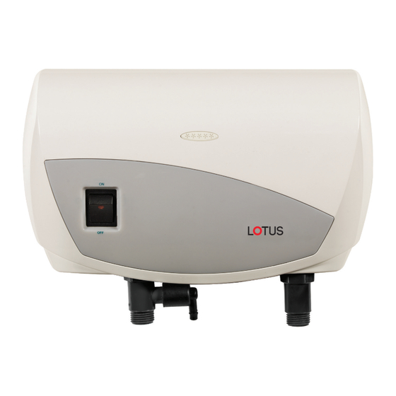
- Page 1 Installation and Operation Guide Model #: LTS-3HP 3.5kW / 120V Note: Restricted to sink applications only. Please read manual completely prior to installing your unit to understand if this unit is suitable for your application.
-
Page 2: Safety Instructions
Safety Instructions OVERVIEW This manual must be read carefully before attempting to install the water heater. If you do not follow the safety rules or the instructions outlined in this manual, the unit may not operate properly and it could cause property damage, serious bodily injury or death. -
Page 3: Technical Information
Model Wattage Voltage Amperage Phase size size LTS-3HP 3.5 kW 10 AWG Minimum water flow to activate unit: 0.5 GPM Nominal water volume: 0.11 gal (0.42l) Working pressure: 0.5 -8 bar (7 -115 psi) Tested pressure: 16 bar (230 psi) Water connections: 1/2”... - Page 4 Assembly Instructions 1. Mount ground plate to wall. Connect the Pressure Relief Device Remove the appliance covers 2. Pull wires through. (PRD) to the unit (Fig1) Note: (Figure 2). 3. Cut out hole in back of unit IMPORTANT – do not discard (Right/Left back) and pass this step.
- Page 5 Rubber Cold G = Green or Yellow N = White L1 = Black 3.5kW...
- Page 6 Connect the power cable to the terminal block. Caution: The heater must be grounded. Reference figure *3 on page 4 and Run the water flow for Electrical diagram on page 6 one minute to check for leakage before connecting to power. Reattach the front cover of the heater and secure it with 4 screws and then slide the bottom gray cover...
-
Page 7: Electrical Diagram
Electrical Diagram 3.5kW (120V)* - Install Line 1 (L1), E(G)-Ground, N (Neutral) E(G) 1. Terminal block . Thermal cut-out with reset 3. Thermal cut-out 4. Light 5. Switch On / Off 6. Relay 7. Heating element 8. Read sensor * 3.5kW/120V = 3.0kW/110V... -
Page 8: Troubleshooting
Operation Guide Flow Rate Chart 35º F Temp Rise - 0.6 GPM 45º F Temp Rise - 0.5 GPM Troubleshooting PROBLEM ISSUE POSSIBLE CAUSE SOLUTION Water not hot Too much water flowing Reduce the flow rate of the water via enough. - Page 9 Troubleshooting PROBLEM ISSUE POSSIBLE CAUSE SOLUTION Heater shut off Interruption of main Check incoming power supply, MCB, during use. electrical supply. switches and supply cabling. If problem persists, call your local manufacturer for assistance. Water ceases to No water supply. Check if the main water line stop flow.
- Page 10 Parts 1. Switch 2. PRD 3. Cold water inlet 4. Hot water outlet (to be connected to the main hot water pipe)
-
Page 12: Limited Warranty
LIMITED WARRANTY Manufacturer warrants to the original owner that our instant water heaters will be free from defects in workmanship and material for a period of TWO YEARS from the date of purchase, and free from leakage for a period of SEVEN YEARS from the date of purchase. Should any part(s) prove to be defective during this period, Manufacturer will be responsible for replacement of the defective part(s) only. - Page 13 Instalación y guía de funcionamiento Modelo #: LTS-3HP 3,5 kW / 120V Nota: Limitado solo para aplicaciones de lavabos. Lea el manual completamente antes de instalar su unidad para comprender si esta unidad es adecuada para su aplicación.
-
Page 14: Instrucciones De Seguridad
Instrucciones de seguridad DESCRIPCIÓN GENERAL Este manual se debe leer atentamente antes de intentar instalar el calentador de agua. Si usted no cumple las reglas de seguridad o las instrucciones detalladas en este manual, la unidad puede no funcionar adecuadamente y puede causar daños a la propiedad, lesiones corporales graves o la muerte. -
Page 15: Información Técnica
Voltaje Amperaje Fase disyuntor requerido LTS-3HP 3,5 kW 10 AWG Flujo mínimo de agua para activar la unidad: 0,5 GPM Volumen de agua nominal: 0,11 galones (0,42 l) Presión de funcionamiento: de 0,5 a 8 bares (de 7 a 115 psi) Presión probada: 16 bares (230 psi) -
Page 16: Instrucciones De Ensamblaje
Instrucciones de ensamblaje 1. Instale la placa de tierra a Conecte el dispositivo de alivio de Retire las cubiertas del la pared. presión a la unidad (Fig. 1). artefacto (Figura 2). 2. Jale los cables. Nota: IMPORTANTE – No omita este paso. - Page 17 Goma Dispositivo de alivio de presión Frío Caliente G = Verde o amarillo N = Blanco L1 = Negro 3,5 kW...
- Page 18 Conecte el cable de alimentación al bloque de terminales. Precaución: el calentador debe estar conectado a tierra. Consulte la figura 3 en la página 4 y el Deje correr el agua durante un diagrama eléctrico en la página 6. minuto para verificar si hay fugas antes de conectar el artefacto al suministro eléctrico.
- Page 19 Electrical Diagram 3,5 kW (120V)* - Instalar Línea 1 (L1), E(G)-Tierra, N (Neutro) E(G) 1. Bloque de terminales 2. Interruptor térmico con reajuste 3. Interruptor térmico 4. Luz 5. Interruptor de Encendido / Apagado 6. Relé 7. Resistencia 8. Sensor de lectura * 3,5 kW / 120V = 3,0 kW / 110V...
-
Page 20: Guía De Funcionamiento
Guía de funcionamiento Guía de aumento de temperature Aumento de temp. de 35 °F - 0,6 GPM Aumento de temp. de 45 °F - 0,5 GPM Resolución de problemas PROBLEMA CAUSA POSIBLE SOLUCIÓN Fluye demasiada agua por Reducir la tasa de flujo del agua El agua no está... - Page 21 Resolución de problemas PROBLEMA CAUSA POSIBLE SOLUCIÓN El calentador se Interrupción del Revisar el suministro de energía, apaga durante suministro eléctrico. disyuntor, interruptores y cableado. el uso. Si el problema persiste, llame a su fabricante local para obtener asistencia. El agua deja de Interrupción del suministro Verificar que la válvula de cierre de la correr.
- Page 22 Piezas 1. Interruptor 2. Dispositivo de alivio de presión 3. Entrada de 4. Salida de agua caliente agua fría (para conectar a la tubería de agua caliente)
-
Page 24: Garantía Limitada
GARANTÍA LIMITADA Fabricante garantiza al propietario original de nuestros calentadores de agua instantáneos la ausencia de defectos de fabricación y material durante un período de DOS AÑOS a partir de la fecha de compra, y la ausencia de fugas durante un período de SIETE AÑOS a partir de la fecha de compra. Si alguna pieza resultara defectuosa durante este período, Fabricante será...
Need help?
Do you have a question about the LTS-3HP and is the answer not in the manual?
Questions and answers