Advertisement
Quick Links
1
9
1
2
1
E
L
T
O
R
O
R
O
A
D
1
9
1
2
1
E
L
T
O
R
O
R
O
A
D
I
N
S
T
R
U
C
I
N
S
T
R
U
C
C
D
N
C
D
N
C
O
U
P
L
I
N
G
C
O
U
P
L
I
N
N
E
T
W
O
N
E
T
W
O
●
S
I
L
V
E
R
A
D
O
,
C
A
L
I
F
O
●
S
I
L
V
E
R
A
D
O
,
C
A
L
I
F
O
C
C
D
D
N
N
M
M
-
-
s
s
e
e
r
r
i
i
e
e
s
s
T
I
O
N
M
A
N
U
A
L
T
I
O
N
M
A
N
U
A
L
f
o
r
f
o
r
M
-
s
e
r
i
e
s
M
-
s
e
r
i
e
s
/
D
E
C
O
U
P
L
I
N
G
G
/
D
E
C
O
U
P
L
I
N
G
R
K
S
(
C
D
N
s
)
R
K
S
(
C
D
N
s
)
R
N
I
A
9
2
6
7
6
●
(
9
4
9
R
N
I
A
9
2
6
7
6
●
(
9
4
9
P
a
g
P
a
I
N
S
T
R
U
C
T
I
O
N
I
N
S
T
R
U
C
T
I
O
N
C
O
U
P
L
I
N
G
/
D
E
C
O
U
P
L
I
N
G
N
E
T
W
C
O
U
P
L
I
N
G
/
D
E
C
O
U
P
L
I
N
G
N
E
T
)
4
5
9
-
9
6
0
0
●
c
o
m
-
p
)
4
5
9
-
9
6
0
0
●
c
o
m
-
p
e
1
o
f
3
8
g
e
1
o
f
3
8
M
A
N
U
A
L
M
A
N
U
A
L
O
R
K
S
(
C
D
N
s
)
W
O
R
K
S
(
C
D
N
s
)
o
w
e
r
.
c
o
m
o
w
e
r
.
c
o
m
Rev072518
Advertisement

Summary of Contents for Com-Power CDN M Series
- Page 1 ● ● ● ● ● ● Rev072518...
- Page 2 ● ● ● ● ● ● Rev072518...
- Page 3 – – – – – – & & ● ● ● ● ● ● Rev072518...
- Page 4 – – & & ● ● ● ● ● ● Rev072518...
- Page 5 Information contained in this manual is the property of Com-Power Corporation. It is issued with the understanding that the material may not be reproduced or copied without the express written permission of Com-Power.
- Page 6 ● ● ● ● ● ● Rev072518...
-
Page 7: Standard Items
CDN or any of its accessories if there is any evidence of shipping damage. If shipping damage to the product or any of the accessories is suspected, or if the package contents are not complete, contact Com-Power or your Com-Power distributor. - Page 8 The hazard symbols appearing on the product exterior are defined below. The yellow triangle with an exclamation mark indicates the presence of important operating and/or maintenance (servicing) instructions in the literature accompanying the product. The yellow triangle with a lightning bolt indicates an alert to the user that uninsulated dangerous voltages are present within the product enclosure and on output connectors.
-
Page 9: Heed Warnings
The following safety instructions have been included in compliance with safety standard regulations. Please read them carefully. • READ AND RETAIN INSTRUCTIONS - Read all safety and operating instructions before operating the instrument. Retain all instructions for future reference. •... -
Page 10: Environmental Conditions
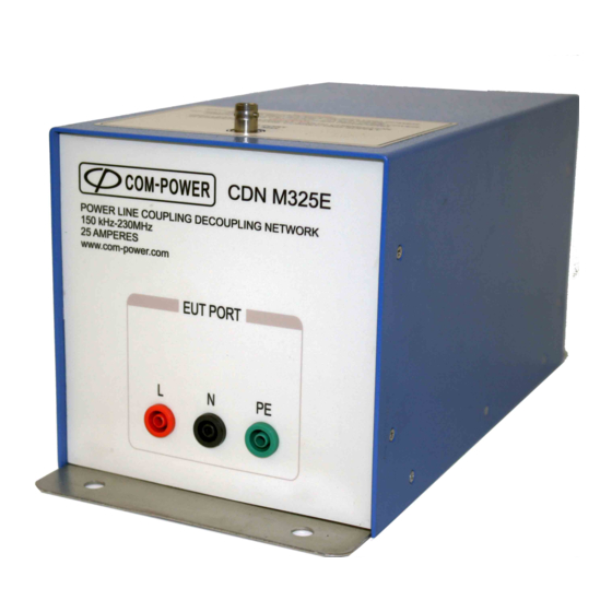
• POWER CORD PROTECTION - Place power supply cords so that they are not likely to be walked on or pinched by items placed on them or against them. • CLEANING – Clean the instrument outside surfaces of the device with a soft, lint-free cloth. - Page 11 – – RF Port This is a coaxial BNC (female) connector for connection to the test generator equipment. EUT Port Port for connection of the EUT power input lines. Depending on the CDN model, this port is fitted with between one (1) and five (5) shrouded power connectors.
- Page 12 13 / 5.9 All values are typical, unless specified. All specifications are subject to change without notice. CDN MxxxE POWER LINE COUPLING/DECOUPLING NETWORK 150 kHz - 230 MHz xxx AMPERES www.com-power.com EUT PORT EUT PORT CDN ADA-MxxxE SHORTING ADAPTER www.com-power.com ●...
- Page 13 1000 Frequency (MHz) 1000 Frequency (MHz) 1000 Frequency (MHz) EUT Port: OPEN EUT Port: SHORT 1000 Frequency (MHz) ● ● ● ● ● ● Rev072518...
- Page 14 The CDN M-series Coupling/Decoupling Networks (CDNs) are specifically designed for immunity to conducted disturbances testing as per IEC 61000-4-6. CDNs provide a standardized common mode impedance for the EUT power lines which is independent of the external power line impedance. The RF test signal is injected via the RF port of the CDN, and is coupled onto the EUT power lines (directly for the PE conductor, and capacitively for all other conductors) through an effective resistance of 100 ohms.
- Page 15 It is critical that the CDN be installed in a manner which ensures that EACH of following conditions are satisfied: • The metal enclosure of the CDN must be connected to the reference ground plane. The recommended connection method is via a direct, surface to surface connection between the CDN base plate and an exposed, conductive surface of the floor or wall of a shielded enclosure.
- Page 16 All Com-Power M-series CDNs are equipped with shrouded safety connectors for both the EUT Port and AE Port. All connections to these ports must be made with mating shrouded safety connectors. The mating connectors for the 50 Amp CDNs are provided. The mating connectors for the 25 Amp and 100 Amp CDNs can be purchased commercially and are commonly available.
- Page 17 To power the EUT through an M-series CDN, follow the step-by-step procedure described in Figure 8. – – P R O D U C T I N S T A L L A T I O N S E C T I O N 4 - 1 9 1 2 1 E l T o r o R d ●...
- Page 18 NOTE: The user is reminded that the applicable standard(s) for your application take precedence over the information contained in this manual. The following information is provided only for guidance; please refer to section 1 for full disclaimer. The M-series CDNs are used only on power lines. The appropriate M-series CDN is selected based on: 1) the DC or AC rms current requirements for the Equipment Under Test (EUT) based on Table 3 below;...
- Page 19 3) the routing of the supply wires in the device’s actual installation, as supply wires that will be individually routed require separate CDN-M1 CDNs for each wire to be installed for the test; and, 4) whether the EUT is provided with functional earth terminals (e.g. for RF purposes or high leakage currents), which shall be connected to the reference ground plane: –...
- Page 20 Calibration of Coupling/Decoupling Networks can be divided into two categories. The first category includes the calibration/measurement of its electrical performance parameters, such as common mode impedance, phase, voltage division factor and, in some cases, isolation (or decoupling attenuation). These calibrations are typically performed on a periodic basis in order to verify that the CDN continues to be in proper working order, (i.e.: functioning within its prescribed specifications and/or in compliance with the applicable requirements.
- Page 21 The impedance/phase is typically measured using an Impedance Analyzer or Network Analyzer with S-parameter Test Set. A typical test setup for analyzer calibration and measurement of impedance/phase is illustrated in Figure 9. Calibration of analyzers is typically performed using the OPEN/SHORT/LOAD (OSL) method, using female BNC standards.
- Page 22 The voltage division factor of a CDN is the difference between the voltage level injected into RF port of the CDN, and the voltage measured at the output of the 150Ω to 50Ω adapter connected to the EUT port of the CDN. See Equation 1. A typical setup for equipment normalization and measurement of the voltage division factor is illustrated in Figure 5.
- Page 23 Isolation, or decoupling attenuation, is the attenuation provided by the CDN between its AE and EUT ports. However, the isolation is measured by injecting a voltage (V ) into the AE port through a 150Ω to 50Ω Adapter, measuring the voltage level at the RF port (V ) with the EUT port open and then shorted to GND (see Figure 11).
- Page 24 This following sections describe the calculations, measurement setups, as well as a step- by-step procedure for performing test level calibration per the IEC 61000-4-6 standard. Test level calibration is typically performed prior to the start of a test, for the purpose of setting the specific level for the test to be performed (i.e.: 1 Vrms, 3 Vrms, 10 Vrms, etc.).
- Page 25 In the following procedures, instructions are included for both methods. Instructions common for both METHOD A METHOD B are shown in BLACK text. Any instructions applicable only for METHOD A are shown in GREEN text. instructions applicable only for METHOD B are shown in BLUE text. For each method, as will be discussed later in this chapter, the test generator equipment is used to inject the test signal into RF port of the CDN.
- Page 26 Prior to the start of the calibration process, U must be calculated. U represents the voltage to be measured at the output of the 150Ω to 50Ω Adapter connected to the EUT port of the CDN, and must not be confused with the open circuit test level (U ) for the calibration (i.e.: 1 Vrms, 3 Vrms, 10 Vrms, etc., as specified in Table 1 of IEC 61000-4-6).
- Page 27 Additionally, shown in Figure 13 are the coaxial cables and attenuator installed between the output of the 150Ω to 50Ω Adapter (where U measured) and the measuring instrument. The calculated U value must be corrected for the attenuation of the attenuator and the insertion losses of Cable #1 and Cable #2 shown in Figure 13.
- Page 28 Using the U Measurement Line calibration results, the U value calculated using Equation 3 can now be corrected using Equation 4. As the calibration results are frequency-dependent, the corrections must be applied with respect to frequency. Again, for calibration to be performed at an open circuit test level of 10 Vrms, and assuming a measured 31 dB loss for the U Measurement Line, which included the 30 dB attenuator and both cables:...
- Page 29 If the CDN will be used for multiple test levels (1 Vrms, 3 Vrms, 10 Vrms, etc.), calibration should be performed at the highest test level. Calibration data for the lower test levels can then be calculated as shown in Equation 5.
- Page 30 The frequency range of the test is, in most cases, 150 kHz to 80 MHz; and, in some cases, 150 kHz to 230 MHz. The calibration and test is performed at discrete, logarithmically spaced frequencies (as opposed to a frequency sweep).
- Page 31 On a conductive ground plane, connect the M-series CDN and Calibration Accessories/Adapters as shown in Figure 15. The bottom surfaces of the CDN, both shorting adapters, and both 150Ω to 50Ω Adapters should be flush against the top surface of the ground plane, and should be either: a) fastened using bolts or screws directly to the ground plane (through their respective mounting holes);...
- Page 32 As shown in Figure 16, complete the calibration setup for METHOD A METHOD B, as appropriate. ● ● ● ● ● ● Rev072518...
- Page 33 With the calibration test setup configured as shown in Figure 16, set the frequency of the signal generator and measuring instrument to 150 kHz (without modulation). WITHOUT exceeding [the 1 dB gain compression point of the power amplifier minus 5.1 dB], adjust the amplitude setting of the signal generator until the amplitude measured on the measuring instrument is equal to the U value (±1.5 dB) calculated as described in...
- Page 34 Set the frequency of the signal generator to 150 kHz (without modulation). Adjust the signal generator output to either: the respective SGout value determined during calibration for the present test frequency. -or- the level at which the power indicated by the power meter is equal to the respective FWDpwr value determined during calibration for the present test frequency.
- Page 35 Examples of typical test setups for METHOD A METHOD B are shown in Figure 17 for an EUT having a single power input port (and no other I/O ports) with one to five power conductors, and no other input/output ports. Test setups for devices having multiple I/O ports are more complex, and usually require multiple CDNs of different types.
- Page 36 The same Test Generator equipment used for the calibration is used to inject the RF energy onto the EUT lines under test via the CDN during the test. With the test setup configured as shown in Figure 17, and/or as required by the applicable standard(s), and with the EUT being exercised as required for the test, set the frequency of the signal generator to 150 kHz, modulated as required (usually 1 kHz AM @ 80%).
- Page 37 Com-Power warrants to its Customers that the products it manufactures will be free from defects in materials and workmanship for a period of three (3) years. This warranty shall not apply to: • Transport damages during shipment from your plant.
-
Page 38: Maintenance
This product contains no user serviceable parts. If the unit does not operate or needs calibration, please contact Com-Power Corporation. Any modifications or repairs performed on the unit by someone other than an authorized factory trained technician will void warranty.
Need help?
Do you have a question about the CDN M Series and is the answer not in the manual?
Questions and answers