
Summary of Contents for SKS Sweden Bonfiglioli Vectron ACTIVE CUBE ACU 201 Series
- Page 1 ACTIVE CUBE Operating Instructions Frequency Inverter 230V / 400V 0.25 kW ... 132 kW...
- Page 3 General Information about the Documentation The present documentation refers to the frequency inverters ACTIVE Cube 201 and ACTIVE Cube 401 series. With their factory settings, both series of devices are suited for a wide range of applications. The modular hardware and software structure enables customer-specific adaptation of the frequency inverters.
- Page 4 The following pictograms and signal words are used in the documentation: Danger! Danger refers to an immediate threat. Non-compliance with the precaution described may result in death, serious injury or material damage. Warning! Warning refers to a possible threat. Non-compliance with the warning may result in death, serious injury or material damage.
-
Page 5: Table Of Contents
TABLE OF CONTENTS General Safety Instructions and Information on Use ..........10 General Information ................. 10 Purpose of the Frequency Inverters ............11 Transport and Storage ................11 Handling and Installation ................. 11 ... - Page 6 5.4.1 Dimensioning of conductor cross-section ............41 5.4.1.1 Typical cross-sections ..................41 5.4.2 Mains Connection .................... 42 5.4.3 Motor Connection .................... 43 5.4.3.1 Length of motor cables, without filter ..............43 ...
- Page 7 Commissioning of the Frequency Inverter ..............81 Switching on Mains Voltage ..............81 Setup Using the Control Unit ..............81 7.2.1 Configuration ....................82 7.2.2 Data Set ......................83 7.2.3 ...
- Page 8 System Data ....................... 112 10.1 Actual System Value ................112 10.2 Volume Flow and Pressure ..............112 Operational Behavior ....................113 11.1 Starting Behavior ..................113 11.1.1 Starting Behavior of Sensorless Control System ..........113 ...
- Page 9 13.10 Motor Potentiometer ................146 13.10.1 Motorpoti (MP) ....................147 13.10.2 Motorpoti (KP) ....................147 13.10.3 Controlling the Motor via the Control Unit ............148 13.11 PWM-/repetition frequency input ............149 ...
- Page 10 16.4 Functions of Sensorless Control.............. 202 16.4.1 Slip compensation ..................202 16.4.2 Current limit value controller ................202 16.5 Functions of Field-Orientated Control ............ 203 16.5.1 Current Controller ..................203 16.5.2 ...
- Page 11 Parameter List ......................243 21.1 Actual Value Menu (VAL) ................ 243 21.2 Parameter Menu (PARA) ................. 246 Index ..........................254 Functions of the control terminals (table) ............... 256 09/08 Operating Instructions ACU 09/08 Operating Instructions ACU...
-
Page 12: General Safety Instructions And Information On Use
General Safety Instructions and Information on Use Warning! The specifications and instructions contained in the documentation must be complied with strictly during installation and commissioning. Only qualified staff who has read the documentation and, in particular, the safety instructions carefully is allowed to carry out installation or commissioning work or to operate the frequency inverters. -
Page 13: Purpose Of The Frequency Inverters
Purpose of the Frequency Inverters Warning! The frequency inverters are electrical drive components intended for installation in industrial plants or machines. Commissioning and start of operation is not allowed until it has been verified that the plant meets the requirements of the EC Machinery Directive 98/37/EEC and EN 60204. -
Page 14: Electrical Connection
Electrical Connection Before any assembly or connection work, discharge the frequency in- Warning! verter. Verify that the frequency inverter is discharged. Do not touch the terminals because the capacitors may still be charged. Comply with the information given in the operating instructions and on the frequency inverter label. -
Page 15: Safety Instructions On Function „Safe Torque Off" (Sto)
Safety Instructions on Function „Safe Torque Off“ (STO) The function „Safe Torque Off“ (STO) is a functional safety provision, i.e. it protects staff from damage, provided that projecting, installation and operation are performed properly. This function does not disconnect the plant from power supply. To disconnect the plant from power supply (for example for service purposes) an „Emergency Stop“... - Page 16 Warning! Dangerous voltage! The safety function “Safe Torque Off ” may only be used if mechanical work is to be performed on the driven machines, not for work on live components. After disconnection of an external DC 24 V power supply, the DC link of the frequency inverter is still connected to mains supply.
-
Page 17: Scope Of Supply
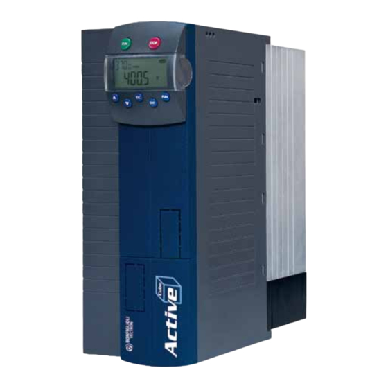
Scope of Supply Thanks to the modular hardware components, the frequency inverters can be inte- grated in the automation concept easily. The scope of delivery described can be sup- plemented by optional components and adapted to the customer-specific require- ments. The plug-in type connection terminals enable a safe function and quick and easy assembly. -
Page 18: Acu 201 (4.0 To 9.2 Kw) And 401 (5.5 To 15.0 Kw)
ACU 201 (4.0 to 9.2 kW) and 401 (5.5 to 15.0 kW) Scope of Supply Scope of Supply Frequency inverter Terminal strip X10 (Phoenix ZEC 1.5/3ST5.0) Plug-in terminals for the relay output Standard fittings with fitting screws (M4x20, M4x60) for vertical assembly Brief Instructions and Operating Instructions on CD ROM Control terminals X210A / X210B (Wieland DST85 / RM3.5) Plug-in terminal for connection of the control signals... -
Page 19: Acu 401 (18.5 To 30.0 Kw)
ACU 401 (18.5 to 30.0 kW) Scope of Supply Scope of Supply Frequency inverter Terminal strip X10 (Phoenix ZEC 1.5/3ST5.0) Plug-in terminals for the relay output Standard fittings with fitting screws (M4x20, M4x70) for vertical assembly Brief Instructions and Operating Instructions on CD ROM Control terminals X210A / X210B (Wieland DST85 / RM3.5) Plug-in terminal for connection of the control signals Please check incoming goods for quality, quantity and nature without... -
Page 20: Acu 401 (37.0 To 65.0 Kw)
ACU 401 (37.0 to 65.0 kW) Scope of Supply Scope of Supply Frequency inverter Terminal strip X10 (Phoenix ZEC 1.5/3ST5.0) Plug-in terminals for the relay output Standard fittings with fitting screws (M5x20) for vertical assembly Brief Instructions and Operating Instructions on CD ROM Control terminals X210A / X210B (Wieland DST85 / RM3.5) Plug-in terminal for connection of the control signals Please check incoming goods for quality, quantity and nature without... -
Page 21: Acu 401 (75.0 To 132.0 Kw)
ACU 401 (75.0 to 132.0 kW) Scope of Supply Scope of Supply Frequency inverter Terminal strip X10 (Phoenix ZEC 1.5/3ST5.0) Plug-in terminals for the relay output Control terminals X210A / X210B (Wieland DST85 / RM3.5) Plug-in terminal for connection of the control signals Brief Instructions and Operating Instructions on CD ROM Please check incoming goods for quality, quantity and nature without Note:... -
Page 22: Technical Data
Technical Data General technical data CE conformity The frequency inverters ACU meet the requirements of the low voltage directive 2006/95/EC and EN 50178/DIN VDE 0160 and EN 61800-2. EMC directive For proper installation of the frequency inverter in order to meet the require- ments of EN 61800-3, please comply with the installation instructions in these operating instructions. -
Page 23: Technical Data - Control Electronic Equipment
Technical Data – Control Electronic Equipment Control terminal X210A Control terminal X210B X210A.1 DC 20 V output (I =180 mA) X210B.1 Digital input or DC 24 V ±10% input for external power supply X210A.2 GND 20 V/ GND 24 V (ext.) X210B.2 Digital input STOB safety... -
Page 24: Acu 201 (0.25 To 1.1 Kw, 230 V)
ACU 201 (0.25 to 1.1 kW, 230 V) Type ACU 201 Construction Size Output, motor side Recommended motor shaft power 0.25 0.37 0.55 0.75 Output current Long-term overload current (60 s) Short-time overload current (1 s) Output voltage Maximum input voltage, three-phase Protection Short circuit / earth fault proof Rotary field frequency... -
Page 25: Acu 201 (1.5 To 3.0 Kw, 230 V)
ACU 201 (1.5 to 3.0 kW, 230 V) Type ACU 201 Construction Size Output, motor side Recommended motor shaft power 4) 5) Output current 12.5 Long-term overload current (60 s) 10.5 14.3 16.2 Short-time overload current (1 s) 14.0 19.0 19.0 Output voltage Maximum input voltage, three-phase... -
Page 26: Acu 201 (4.0 To 9.2 Kw, 230 V)
ACU 201 (4.0 to 9.2 kW, 230 V) Type ACU 201 Construction Size Output, motor side Recommended motor shaft power Output current 18.0 22.0 32.0 35.0 Long-term overload current (60 s) 26.3 30.3 44.5 51.5 Short-time overload current (1 s) 33.0 33.0 64.0... -
Page 27: Acu 401 (0.25 To 1.5 Kw, 400 V)
ACU 401 (0.25 to 1.5 kW, 400 V) Type ACU 401 Construction Size Output, motor side Recommended motor shaft power 0.25 0.37 0.55 0.75 Output current Long-term overload current (60 s) Short-time overload current (1 s) Output voltage Maximum input voltage, three-phase Protection Short circuit / earth fault proof Rotary field frequency... -
Page 28: Acu 401 (1.85 To 4.0 Kw, 400 V)
ACU 401 (1.85 to 4.0 kW, 400 V) Type ACU 401 Construction Size Output, motor side Recommended motor shaft power 1.85 Output current Long-term overload current (60 s) 11.7 13.5 Short-time overload current (1 s) 11.6 15.6 18.0 Output voltage Maximum input voltage, three-phase Protection Short circuit / earth fault proof... -
Page 29: Acu 401 (5.5 To 15.0 Kw, 400 V)
ACU 401 (5.5 to 15.0 kW, 400 V) Type ACU 401 Construction Size Output, motor side Recommended motor shaft power 11.0 15.0 Output current 14.0 18.0 22.0 25.0 32.0 Long-term overload current (60 s) 21.0 26.3 30.3 37.5 44.5 Short-time overload current (1 s) 28.0 33.0 33.0... -
Page 30: Acu 401 (18.5 To 30.0 Kw, 400 V)
ACU 401 (18.5 to 30.0 kW, 400 V) Type ACU 401 Construction Size Output, motor side Recommended motor shaft power 18.5 22.0 30.0 Output current 40.0 45.0 60.0 Long-term overload current (60 s) 60.0 67.5 90.0 Short-time overload current (1 s) 80.0 90.0 120.0... -
Page 31: Acu 401 (37.0 To 65.0 Kw, 400 V)
3.10 ACU 401 (37.0 to 65.0 kW, 400 V) Type ACU 401 Construction Size Output, motor side Recommended motor shaft power 37.0 45.0 55.0 65.0 Output current 75.0 90.0 110.0 125.0 Long-term overload current (60 s) 112.5 135.0 165.0 187.5 Short-time overload current (1 s) 150.0 180.0... -
Page 32: Acu 401 (75.0 To 132.0 Kw, 400 V)
3.11 ACU 401 (75.0 to 132.0 kW, 400 V) Type ACU 401 Construction Size Output, motor side Recommended motor shaft power Output current Long-term overload current (60 s) Short-time overload current (1 s) Output voltage Maximum input voltage, three-phase Protection Short circuit / earth fault proof Rotary field frequency 0 ... -
Page 33: Operation Diagrams
3.12 Operation diagrams The technical data of the frequency inverters refer to the nominal point which was selected to enable a wide range of applications. A functionally and efficient dimension- ing (derating) of the frequency inverters is possible based on the following diagrams. Installation height Power reduction (Derating), max. -
Page 34: Mechanical Installation
Mechanical Installation The frequency inverters of degree of protection IP20 are designed, as a standard, for installation in electrical cabinets. During installation, both the installation and the safety instructions as well as the • device specifications must be complied with. Warning! To avoid serious physical injuries or major material damage, only quali- fied persons are allowed to work on the devices. -
Page 35: Acu 201 (4.0 To 9.2 Kw) And 401 (5.5 To 15.0 Kw)
ACU 201 (4.0 to 9.2 kW) and 401 (5.5 to 15.0 kW) The frequency inverter is mounted in a vertical position on the assembly panel by means of the standard fittings. The following illustration shows the standard fitting. Standard installation 100 mm ≥... -
Page 36: Acu 401 (18.5 To 30.0 Kw)
ACU 401 (18.5 to 30.0 kW) The frequency inverter is mounted in a vertical position on the assembly panel by means of the standard fittings. The following illustration shows the standard fitting. Standard installation ≥ 100 mm fixing bracket top fixing bracket bottom (fixing with screws M4x20... -
Page 37: Acu 401 (37.0 To 65.0 Kw)
ACU 401 (37.0 to 65.0 kW) The frequency inverter is mounted in a vertical position on the assembly panel by means of the standard fittings. The following illustration shows the standard fitting. Standard installation ≥ 100 mm fixing braket bottom fixing braket top M5x20 (fixing with screws... -
Page 38: Acu 401 (75.0 To 132.0 Kw)
ACU 401 (75.0 to 132.0 kW) The frequency inverter is mounted in a vertical position on the assembly panel. The following illustration shows the standard fitting. Standard installation 300 mm 300 mm The diameter of the fixing holes is 9 mm. Assembly is done by screwing the back wall of the frequency inverter to the assembly panel. -
Page 39: Electrical Installation
Electrical Installation The electrical installation must be carried out by qualified staff according to the gen- eral and regional safety and installation directives. For a safe operation of the fre- quency inverter it is necessary that the documentation and the device specifications be complied with during installation and commissioning. -
Page 40: Emc Information
EMC Information The frequency inverters are designed according to the requirements and limit values of product norm EN 61800-3 with an interference immunity factor (EMI) for operation in industrial applications. Electromagnetic interference is to be avoided by expert installation and observation of the specific product information. Measures •... -
Page 41: Block Diagram
Block diagram S3OUT L2 L3 X210A +20 V / 180 mA 24 V GND 20 V S1IND S2IND S3IND U, I S4IND S5IND X210B S6IND S7IND S1OUT MFO1 +10 V / 4 mA MFI1 GND 10 V Relay connection S3OUT Change-over contact, response time approx. -
Page 42: Optional Components
Optional Components Thanks to the modular hardware components, the frequency inverters can be inte- grated in the automation concept easily. The standard and optional modules are rec- ognized during the initialization, and the controller functionality is adjusted automati- cally. For the information required for installation and handling of the optional mod- ules, refer to the corresponding documentation. -
Page 43: Connection Of Unit
Connection of Unit 5.4.1 Dimensioning of conductor cross-section The cable dimensions should be selected according to the current load and voltage drop to be expected. Select the cable cross-section of the cables such that the voltage drop is as small as possible. If the voltage drop is too great, the motor will not reach its full torque. -
Page 44: Mains Connection
230 V: Three-phase connection (L1/L2/L3) Mains cable PE-conductor Motor cable 0.25 kW 0.37 kW 0.55 kW 0.75 kW 2x1.5 mm² or 1.5 mm² 1.5 mm² 1.1 kW 1x10 mm² 1.5 kW 2.2 kW 3 kW 4 kW 2x4 mm² or 4 mm²... -
Page 45: Motor Connection
5.4.3 Motor Connection BONFIGLIOLI VECTRON recommends using shielded cables for the connection of the motor and the brake resistor to the frequency inverter. The shield is to be connected to PE potential properly, i.e. with good conductivity, on both sides. The control, mains and motor lines must be kept physically separate from one another. -
Page 46: Group Drive
5.4.3.4 Group drive In the case of a group drive (several motors at one frequency inverter), the total length shall be divided across the individual motors according to the value given in the table. Please note that group drive with synchronous servomotors is not possible. Use a thermal monitoring element on each motor (e.g. -
Page 47: Connection Of Types
Connection of types 5.5.1 ACU 201 (up to 3.0 kW) and 401 (up to 4.0 kW) The mains connection of the frequency inverter is via plug-in terminal X1. The con- nection of motor and brake resistor to the frequency inverter is done via plug-in ter- minal X2. - Page 48 Motor connection ACU 201 (up to 3.0 kW) and 401 (up to 4.0 kW) Phoenix ZEC 1,5/ .. ST7,5 0.2 … 1.5 mm AWG 24 … 16 0.2 … 1.5 mm AWG 24 … 16 0.25 … 1.5 mm AWG 22 … 16 0.25 …...
-
Page 49: Acu 201 (4.0 To 9.2 Kw) And 401 (5.5 To 15.0 Kw)
5.5.2 ACU 201 (4.0 to 9.2 kW) and 401 (5.5 to 15.0 kW) Danger! Switch off power supply before connecting or disconnecting the mains cable to/from terminal X1, the motor cables and the brake resis- tor to/from terminal X2. The terminals may be live even after discon- nection of the frequency inverter from power supply. - Page 50 Motor connection ACU 201 (4.0 to 9.2 kW) and 401 (5.5 to 15.0 kW) Delta connection Star connection 4.0 kW … 9.2 kW 11.0 kW … 15.0 kW 6qmm / RM7,5 16qmm / RM10+15 0.2 … 6 mm 0.2 … 16 mm AWG 24 …...
-
Page 51: Acu 401 (18.5 To 30.0 Kw)
5.5.3 ACU 401 (18.5 to 30.0 kW) Danger! Switch off power supply before connecting or disconnecting the mains cable to/from terminal X1, the motor cables and the brake resis- tor to/from terminal X2. The terminals may be live even after discon- nection of the frequency inverter from power supply. - Page 52 Motor connection ACU 401 (18.5 to 30.0 kW) 2.5 Nm 22.1 lb-in 18.5 kW … 30 kW 25/ 6-15,00 0.5 … 35 mm AWG 20 … 2 0.5 … 25 mm AWG 20 … 4 1.00 … 25 mm AWG 18 … 4 1.5 …...
-
Page 53: Acu 401 (37.0 To 65.0 Kw)
5.5.4 ACU 401 (37.0 to 65.0 kW) Danger! Switch off power supply before connecting or disconnecting the mains cable to/from terminal X1, the motor cables and the brake resis- tor to/from terminal X2. The terminals may be live even after discon- nection of the frequency inverter from power supply. - Page 54 Motor connection ACU 401 (37.0 to 65.0 kW) 37.0 kW … 65.0 kW threaded bolt M8x25 wire cross section up to 70 mm 8 Nm 70.8 lb-in Star connection Delta connection Connection of brake resistor with temperature switch 37.0 kW … 65.0 kW threaded bolt M8x25 Wire cross section up to 70 mm 8 Nm...
-
Page 55: Acu 401 (75.0 To 132.0 Kw)
5.5.5 ACU 401 (75.0 to 132.0 kW) Danger! Switch off power supply before connecting or disconnecting the mains cable, the motor cables and the brake resistor. The terminals may be live even after disconnection of the frequency inverter from power supply. Wait for some minutes until the DC link capacitors have discharged before starting the work. - Page 56 Motor connection ACU 401 (75.0 to 132 kW) 10 Nm 88.5 lb-in Star connection Delta connection Threaded bolt M8x20 Connection of brake resistor with temperature switch 10 Nm 88.5 lb-in Threaded bolt M8x20 Optional, the inverters in this size can be purchased without brake Note: chopper and are then not provided with the terminal Rb2 for a brake resistor connection.
-
Page 57: Control Terminals
Control Terminals The control and software functionality can be configured as required to ensure a reliable and economical operation. The operating instructions describe the factory Configuration settings of the standard connections in the relevant 30 as well as the software parameters to be set up. Caution! Switch off power supply before connecting or disconnecting the keyed control inputs and outputs. - Page 58 Control terminal X210A Ter. Description - Voltage output 20 V, I =180 mA - input for external power supply DC 24 V ±10% GND 20 V and GND 24 V (ext.) Digital signal, STOA (1st shutdown path for safety function STO – „Safe Torque Off “), U =DC 30 V, 10 mA at DC 24 V, input resistance: 2.3 kΩ, PLC compati- ble, response time approx.
-
Page 59: External Dc 24 V Power Supply
5.6.1 External DC 24 V power supply The bidirectional control terminals X210A.1/ X210A.2 can be used as a voltage output or voltage input. By connecting an external power supply of DC 24 V ±10% to ter- minals X210A.1/X210A.2, the function of inputs and outputs as well as the communi- cation can be maintained. -
Page 60: Control Terminals - Connection Diagrams Of Configurations
5.6.4 Control terminals – Connection diagrams of configura- tions The control hardware and the software of the frequency inverter are freely configur- able to a great extent. Certain functions can be assigned to the control terminals, and the internal logic of the software modules can be freely selected. Thanks to the modular design, the frequency inverter can be adapted to a great range of different driving tasks. -
Page 61: Configuration 110 - Sensorless Control
5.7.1 Configuration 110 – Sensorless Control Configuration 110 contains the functions for variable-speed control of a 3-phase ma- chine in a wide range of standard applications. The motor speed is set according to the selected ratio of the reference frequency to the necessary voltage. Control terminal X210A X210A.1 Voltage output +20 V or input for... -
Page 62: Configuration 410 - Sensorless Field-Oriented Control
5.7.3 Configuration 410 – Sensorless Field-Oriented Control Configuration 410 contains the functions for sensorless, field-oriented control of a 3- phase machine. The current motor speed is determined from the present currents and voltages in combination with the machine parameters. Separate control of torque and flux-forming current enables a high drive dynamics at a high load moment. -
Page 63: Configuration 411 - Sensorless Field-Oriented Control With Technology
5.7.4 Configuration 411 – Sensorless Field-Oriented Control with Technology Controller Configuration 411 extends the functionality of the sensorless field-oriented control of Configuration 410 by a Technology Controller. The Technology Controller enables a control based on parameters such as flow rate, pressure, filling level or speed. Control terminal X210A X210A.1 Voltage output +20 V or input for... -
Page 64: Controlled
5.7.5 Configuration 430 – Sensorless Field-Oriented Control, Speed and Torque Controlled Configuration 430 extends the functionality of the sensorless field-oriented control of Configuration 410 by a Torque Controller. The reference torque is represented as a percentage and it is transmitted into the corresponding operational performance of the application. -
Page 65: Configuration 210 - Field-Oriented Control, Speed Controlled
5.7.6 Configuration 210 – Field-Oriented Control, Speed Con- trolled Configuration 210 contains the functions for speed-controlled, field-oriented control of a 3-phase machine with speed sensor feedback. The separate control of torque and flux-forming current enables high drive dynamics with a high load moment. The necessary speed sensor feedback results in a precise speed and torque performance. -
Page 66: Configuration 230 - Field-Orientated Control, Speed And Torque Controlled
5.7.8 Configuration 230 – Field-Orientated Control, Speed and Torque Controlled Configuration 230 extends the functionality of Configuration 210 by functions for torque-dependent, field-oriented control. The reference torque is represented as a percentage and it is transmitted into the corresponding operational performance of the application. -
Page 67: Configuration 510 - Field-Oriented Control Of Synchronous Machine
5.7.9 Configuration 510 – Field-Oriented Control of Syn- chronous Machine, Speed Controlled Configuration 510 contains the functions for speed-controlled, field-oriented control of a synchronous machine with resolver feedback. The separate control of torque and flux-forming current enables high drive dynamics with a high load moment. The ne- cessary resolver feedback results in a precise speed and torque performance. -
Page 68: Configuration 530 - Field-Orientated Control Of A Synchronous Machine
5.7.10 Configuration 530 – Field-Orientated Control of a Syn- chronous Machine, Speed and Torque Controlled Configuration 530 extends the functionality of Configuration 510 by functions for torque-dependent, field-oriented control. The reference torque is represented as a percentage and it is transmitted into the corresponding operational performance of the application. -
Page 69: Control Unit Kp500
Control Unit KP500 The optional KP500 control unit is a practical tool for controlling the frequency inver- ter and setting and displaying the frequency inverter parameters. The control unit is not absolutely necessary for the operation of the frequency inver- ter and can be plugged on when required. -
Page 70: Menu Structure
Menu Structure The menu structure of the control unit is arranged as shown in the following illustra- tion. Use the arrow keys as well as ESC and ENT to navigate through the menu. The software contains the full set of information and enables a flexible use of the parame- ter setting and control options. -
Page 71: Actual Value Menu (Val)
Actual Value Menu (VAL) In the VAL menu branch, the control unit displays a variety of actual values, depend- ing on the configuration selected and the options installed. The parameters and basic software functions linked to the corresponding actual value are documented in the operating instructions. -
Page 72: Parameter Menu (Para)
Parameter Menu (PARA) The parameters to be configured during the guided commissioning procedure were selected from common applications and can be supplemented as required by further settings in the PARA menu branch. The parameters and basic software functions linked to the corresponding actual value are documented in the operating instruc- tions. -
Page 73: Copy Menu (Cpy)
Copy Menu (CPY) With the copy function of the control unit you can copy parameter values from the frequency inverter to a non-volatile memory of the control unit (upload) and store (download) them to a frequency inverter again. The copy function makes the parameterization of recurring applications much easier. The function archives all parameter values, regardless of access control and value range. -
Page 74: Menu Structure
6.5.2 Menu Structure The copy menu CPY contains three main functions. Use the arrow keys to select the required function. Select the source and the destination for the process. The memory space available in the non-volatile memory of the control unit is displayed on the three-digit seven-segment display as a percentage value. -
Page 75: Selecting The Destination
6.5.4 Selecting the Destination Select the destination (dSt.) of the copy operation (application-specific). The data source is transferred to the selected target (download). Use the arrow keys to select the destination (dSt.) of the copied data (down- • load). Depending on the data source selected, either the data sets of the fre- quency inverter (dSt. -
Page 76: Error Messages
6.5.6 Error Messages The copy function archives all parameters, regardless of the access control and the value range. Some of the parameters are only writable if the frequency inverter is not in operation. The controller enable input (S1IND/STOA, S7IND/STOB) may not be activated during the copy operation, otherwise the data transmission is aborted. -
Page 77: Reading Data From Control Unit
Reading Data From Control Unit „Parameter transmission“ enables the transmission of parameter values from the control unit KP 500 to the frequency inverter. In this operation mode, all other func- tions of the control unit are disabled, except for the COPY function. Transmission from the frequency inverter to the control unit is also disabled. -
Page 78: Data Transfer
Activation via communication module CM Attention! Activation of the control unit through a communication connection is possible only if the frequency inverter is fitted with an optional commu- nication module CM, and communication takes place via this module. The control unit must be connected to the frequency inverter. •... -
Page 79: Resetting To Normal Operation
6.6.3 Resetting to Normal Operation A control unit KP 500 activated for parameter transmission can be reset to full func- tionality (standard operation) via a specific key code on the control unit or via each available communication module CM. Resetting on control unit Press RUN and STOP keys on control unit simultaneously for approx. -
Page 80: Controlling The Motor Via The Control Unit
In the CTRL menu branch, various functions are available which make commissioning easier and enable the control of the inverter via the control unit. The frequency inverters can be controlled by means of the control unit and/or a communication module. If you want to control the frequency inverter via an optional communication module, Local/Remote the necessary adjustments can be made via parameter... - Page 81 The CTRL menu branch can be accessed via the navigation within the menu structure. The CtrL function contains sub- functions which are displayed according to the operating point of the frequency inverter. Pressing the RUN key leads to a direct change from anywhere within the menu structure to the motorpoti function Pot clockwise rotation or Potr for anticlockwise rotation.
- Page 82 Key functions Reversal of the sense of rotation independent of the control signal on the terminals Clockwise S2IND or Anticlockwise S3IND. Cancel function and return to the menu structure. Switch from internal set point int or motor potentiometer function Pot to JOG frequency;...
-
Page 83: Commissioning Of The Frequency Inverter
Commissioning of the Frequency Inverter Switching on Mains Voltage After completion of the installation work, make sure to check all control and power connections again before switching on the mains voltage. If all electrical connections are correct, make sure that the frequency inverter is not enabled (control inputs S1IND/STOA and S7IND/STOB open). -
Page 84: Configuration
• Switch to the next parameter. • After initialization, confirm the selected configuration by pressing the ENT key. • Continue the guided commissioning procedure according to the following chap- ters. 7.2.1 Configuration Configuration Parameter 30 determines the assignment and basic function of the control inputs and outputs as well as the software functions. -
Page 85: Data Set
Configuration 211, field-oriented control with technology controller Configuration 211 extends the functionality of Configuration 210 by a Technology Controller. The Technology Controller enables a control based on parameters such as flow rate, pressure, filling level or speed. Configuration 230, field-oriented control with speed/torque control Configuration 230 extends the functionality of Configuration 210 by functions for torque-dependent, field-oriented control. -
Page 86: Motor Type
7.2.3 Motor Type The properties of the control functions and methods to be set vary depending on the Motor type motor which is connected. The parameter 369 offers a range of motor variants with the corresponding values. The verification of the entered rated values and the guided commissioning are carried out on the basis of the parameterized motor type. -
Page 87: Plausibility Check
BONFIGLIOLI BN 90LA Motor Example: Parameter Star Delta Rated voltage 400 V 230 V Rated current 3.7 A 6.4 A Rated speed 1410 min 1410 min Rated cosine Phi 0.77 0.77 Rated frequency 50 Hz 50 Hz Rated mechanical power 1.5 kW 1.5 kW 7.2.5 Plausibility check... - Page 88 If an error message is displayed, the rated values must be checked and corrected. The guided commissioning procedure is repeated until the rated values have been entered correctly. Aborting the guided commissioning procedure by pressing ESC key should only be done by expert users because it may be possible that rated val- ues have not been entered or determined correctly.
-
Page 89: Parameter Identification
7.2.6 Parameter identification In addition to the parameterized rated data, the selected configuration demands knowledge of further machine data not stated on the rating plate of the three-phase machine. In addition to entering the rated motor parameters or as an alternative, the required machine data can also be measured during the guided commissioning process. - Page 90 After completion of the parameter identification, warning messages may be dis- played. Depending on the warning message code, the following instructions should be fol- lowed and the measures indicated should be taken. Warning Messages Code Measures / Remedy SA011 Current Controller non typical value; refer to 16.5.1. SA012 Current Controller non typical value with 2 kHz;...
-
Page 91: Application Data
After completion or during the parameter identification, error messages may be dis- played. Depending on the error code, the following instructions should be followed and the measures indicated should be taken. Error Messages Code Measures / Remedy SF011 The main inductance measurement has failed because the motor has a high slip. -
Page 92: Set Points At Multi-Functional Input
7.2.7.2 Set points at multi-functional input The multi-functional input MFI1 can be parameterized for a reference value signal in Operation mode 452. Operation mode 3 should only be selected by expert users for Fixed frequency 1 Fixed frequency 2 drive control via 480 and 481. -
Page 93: Selection Of An Actual Value For Display
7.2.9 Selection of an actual value for display Actual frequency After commissioning, the value of parameter 241 is displayed at the control unit KP500. If another actual value is to be displayed after a restart, make the following settings: Use the arrow keys to select the actual value to be displayed as from now. •... -
Page 94: Speed Sensor
Speed sensor For some configurations an incremental speed sensor must be connected. Dependent on the speed sensor type it can be connected to the basic device or to an expansion module. Some applications require the connection to the basic device as well as to the expansion module. -
Page 95: Speed Sensor 2
7.4.2 Speed sensor 2 Speed sensor 2 must be connected to an expansion module. For connection, func- tions and detailed parameter description refer to the applicable operation instructions manual of the expansion module. Parameter Settings Description Min. Max. Fact. Operation Mode speed sensor 2 Selection Division Marks speed sensor 2 8192... -
Page 96: Set-Up Via The Communication Interface
Set-up via the Communication Interface Parameter-setting and commissioning of the frequency inverter via one of the op- tional communication interfaces include the plausibility check and the parameter identification functions. The parameters can be adjusted by qualified users. The pa- rameter selection during the guided commissioning procedure includes the basic pa- rameters. - Page 97 SETUP Selection Function Further motor data are measured, dependent pa- Calc. and para ident., 33 - rameters are calculated and the parameter values are saved in data set 3. Further motor data are measured, dependent pa- Calc. and para ident., 34 - rameters are calculated and the parameter values are saved in data set 4.
- Page 98 Warning Messages Code Message Meaning Rated voltage The value of the parameter 370 is out of the rated voltage range of the frequency inverter. The maximum SA001 Rated voltage reference voltage is indicated on the nameplate of the fre- quency inverter. For a three-phase motor, the calculated efficiency is in the limit range.
-
Page 99: Inverter Data
Inverter Data The series ACU frequency inverters are suited for a wide range of applications. The modular hardware and software structure enables customer-specific adaptation. The available hardware functionality of the frequency inverter is displayed in the control unit and the optional control software VPlus. The software parameters can be ad- justed to meet the requirements of the specific application. -
Page 100: Control Level
Control Level Control level 28 defines the scope of the functions to be parameterized. The op- erating instructions describe the parameters on the third control level. These parame- ters should only be set by qualified users. Parameter Settings Description Min. Max. - Page 101 Configuration 430, sensorless field-oriented control with speed/torque control Configuration 430 extends the functionality of Configuration 410 by functions for torque-dependent, field-oriented control. The reference torque is represented as a percentage and it is transmitted into the corresponding operational performance of the application.
- Page 102 In the table, you will find a list of functions which are available in the different configurations. Configuration Characte- field-oriented control ristic Servo sensorless sensorless sensor Function Chapter 410 411 430 210 211 230 Speed control 16.5.3 Torque control 16.5.2 Switch-over speed 14.4.6 /torque control...
-
Page 103: Language
Language The parameters are stored in the frequency inverter in various languages. The para- meter description is displayed by the PC control software (e.g. VPlus) in the selected Language Language Function 0 - Deutsch Parameter description in German. 1 - English Parameter description in English. -
Page 104: Machine Data
Machine Data The input of the machine data is the foundation for the functionality of the control functions and methods. In the course of the guided commissioning, the necessary Configuration parameters are inquired according to the selected Rated Motor Parameters Set the rated parameters of the three-phase asynchronous machine according to the rating plate or the data sheet of the motor. -
Page 105: Further Motor Parameters
Further motor parameters In particular the field-oriented control requires the determination of further data which cannot be read off the rating plate of the 3-phase machine for the precise calculation of the machine model. In the course of the guided commissioning, the parameter identification was carried out to measure the further motor parameters. -
Page 106: Magnetizing Current
9.2.3 Magnetizing Current Rated magnetizing current 716 is a measure of the flux in the motor and thus of the voltage which is present at the machine in no-load condition depending on the Rated speed. The guided commissioning determines this value at about 30% of the current 371. -
Page 107: Voltage Constant
9.2.5 Voltage constant In configuration 5xx for the control of synchronous machines, the control behavior can be improved for high dynamic requirements by the settings of the parameter Voltage constant 383. For the voltage constant, refer to the motor data sheet. In the motor data sheet, the value may be indicated in . -
Page 108: Change Sense Of Rotation
9.2.8 Change sense of rotation Change sense of rotation The parameter 1199 reverses the rotating direction of the motor. Operation mode 1199 Positive Set value Negative Set value Motor rotates forward Motor rotates reverse 0 - Off (clockwise) (anti clockwise) Motor rotates reverse Motor rotates forward 1 - On... -
Page 109: Speed Sensor 1
Speed Sensor 1 The frequency inverters are to be adapted to the application depending on the re- Configuration quirements. A part of the available 30 demand continuous measure- ment of the actual speed for the control functions and methods. The necessary con- nection of an incremental speed sensor is done on the digital control terminals S5IND (track A) and S4IND (track B) of the frequency inverter. - Page 110 Operation mode Function Two-channel speed sensor with recognition of direc- Single evaluation tion of rotation via track signals A and B, reference 1001 – with reference track track via digital input S6IND. One signal edge is eva- luated per division mark. Two-channel speed sensor with recognition of direc- Double evaluation tion of rotation via track signals A and B, reference...
-
Page 111: Division Marks, Speed Sensor 1
Attention! In configurations 210, 211 and 230, digital input S4IND is by default set for the evaluation of a speed sensor signal (track B). Operation Mode If an operation mode without sign is selected ( 11 or Operation Mode 12), this input is not set for the evaluation of a speed sensor signal and can be used for other functions. -
Page 112: Gear Factor Speed Sensor 1
9.4.3 Gear factor speed sensor 1 EC1 Gear Factor Numerator EC1 Gear Factor De- Setting of parameters 511 and nominator 512 is required if a gear is installed between the speed sensor and the motor shaft. The parameters define the mechanical transmission ratio between the speed sensor and the motor side. -
Page 113: Sensor Evaluation
Sensor evaluation In the field of drive engineering, TTL and HTL sensors with 512, 1024 or 2048 divi- sion marks are widely used. However, other division mark values are used, too. These division marks (often also referred to as „increments“) determine the resolu- tion (accuracy) at which a machine can be operated. -
Page 114: System Data
System Data Configuration The various control functions and methods according to the selected 30 are supplemented by control and special functions. For monitoring the applica- tion, process parameters are calculated from electrical control parameters. 10.1 Actual System Value Actual system value factor The parameter 389 can be used if the drive is monitored Actual system value... -
Page 115: Operational Behavior
Operational Behavior The operational behavior of the frequency inverter can be adjusted to the application by setting the parameters appropriately. In particular the acceleration and decelera- Configuration tion behavior can be selected according to the selected 30. Additional- ly, features such as Auto Start, and the synchronization and positioning functions facilitate the integration in the application. - Page 116 Operation mode Starting Behavior In this operation mode, the current set with the parame- Current during flux-formation 781 is impressed into the motor for magnetization after release. The output Maximum flux- frequency is kept at zero Hz for the formation time 780.
-
Page 117: Starting Current
11.1.1.1 Starting Current Configurations 110, 111 and 410, 411 and 430 for control of a 3-phase machine use the starting current impression in operation modes 2, 4, 12 and 14 for the parameter Operation mode Starting current 620. The 623 guarantees, in particular for high Frequency limit start torque, sufficient torque to reach the 624. -
Page 118: Flux Formation
11.1.2 Flux Formation Field-oriented control in the configurations 210, 211, 230, 410, 411 and 430 are based on separate regulation of the flux-forming and torque-forming current compo- nents. Upon startup, the machine is magnetized and a current is impressed first. With Current during flux formation the parameter 781 the magnetization current I... -
Page 119: Stopping Behavior
11.2 Stopping Behavior The stopping behavior of the three-phase machine can be defined via parameter Operation mode Start 630. Via the logic signals or digital inputs for the parameters clockwise Start anticlockwise 68 and 69, stopping is activated. Assign digital inputs Configuration or logic signals to these parameters. - Page 120 Stopping Behavior Stopping behavior 0 The inverter is disabled immediately. The drive deener- gized immediately and coasts freely. Free stopping The drive is brought to a standstill at the set decelera- tion. As soon as the drive is at a standstill, the inverter is disabled after a after a holding time.
-
Page 121: Switch-Off Threshold
11.2.1 Switch-Off Threshold Switch-off threshold stop function 637 defines the frequency as from which a standstill of the drive is recognized. This percentage parameter value is relative to Maximum frequency the set 419. The switch-off threshold is to be adjusted according to the load behavior of the drive and the device output, as the drive must be controlled to a speed below the switch- off threshold. -
Page 122: Auto Start
Contact-controlled: Braking time If the parameter 632 is set to the value 0.0 s, the direct current brake is controlled by the Start clockwise and Start anticlockwise signals. The time monitor- Braking time ing and limitation by 632 are deactivated. The braking current will be impressed until the controller enable control signal (S1IND/STOA and S7IND/STOB) becomes logical 0 (low). -
Page 123: Search Run
11.5 Search Run The synchronization to a rotating drive is necessary in applications which drive the motor by their behavior or in which the drive is still rotating after a fault switch-off. Operation mode search run 645, the motor speed is synchronized to the current motor speed without an "Overcurrent"... -
Page 124: Positioning
The synchronization changes the parameterized starting behavior of the selected configuration. First, the start command activates the search run in order to determine Current / Rated the rotary frequency of the drive. In operation modes 1 to 5, the motor current Rated cur- 647 is used for synchronization as a percentage of the rent... -
Page 125: Reference Positioning
The function "Axle positioning" is available in configurations 210 and 510 (Parameter Configuration 30) and is activated by selecting operation mode 2 for parameter eration mode 458. Operation mode Function 0 - Off Positioning switched off. Positioning from reference point via definition of positioning distance (rotations). - Page 126 The digital signal for registration of the reference point and the logical assignment ignal source are to be chosen from a selection of S 459. The link of the digital inputs S2IND, S3IND and S6IND to further functions is to be checked according to selected Configuration 30 (e.g., in configurations 110 and 210, digital input S2IND is linked to the function "Start of clockwise operation").
- Page 127 The behavior of the positioning after the required position of the drive is reached can Activity after positioning be defined via the 463 parameter. Activity after positioning Function The drive is stopped with the stopping behavior 0 - End positioning Operation mode 630.
-
Page 128: Axle Positioning
Examples of reference positioning as a function of the parameter settings selected. Signal sources − The reference point is registered according to the 459 parameter in operation mode 16–S6IND, pos. edge by a signal on digital input 6. Positioning distance 460 with parameter value 0.000U (default) defines a −... - Page 129 The positioning is started by a start command from a signal source (e.g. digital input) Start Positioning of Axle which must be assigned to the parameter 37. The signal source can be selected from the operation modes for digital inputs described in chap- ter "Digital inputs".
- Page 130 If the positioning is carried out, after controller enabling and start command, when the motor is at a standstill: − The motor is positioned clockwise to the reference orientation if the value for the reference orientation is higher than the value adjusted before. −...
-
Page 131: Error And Warning Behavior
Error and warning behavior Operation of the frequency inverter and the connected load are monitored conti- nuously. The monitoring functions are to be parameterized with the corresponding limit values specific to the application. If the limits were set below the switch-off limit of the frequency inverter, a fault switch-off can be prevented by suitable measures if a warning message is issued. -
Page 132: Controller Status
Output signals Digital signals indicate the attainment of warning limits. Warning Limit Heat Sink 166 - Warning Heat Sink The value “80 °C minus Temp. Temperature 407” is attained. Warning Limit Inside Temp. 167 - Warning Inside The value “65 °C minus Temperature 408”... -
Page 133: Frequency Switch-Off Limit
12.5 Frequency Switch-Off Limit The maximum allowed output frequency of the frequency inverter can be set with the Frequency switch-off limit parameter 417. If this frequency limit is exceeded by the Stator frequency Actual frequency 210 or 241, the frequency inverter switches off with fault message “F1100”. -
Page 134: Phase Failure
max.Temp. Windings If the temperature value 617* is exceeded a warning or an Motor Temp. Operation Mode error switch-off is initiated according to 570. Parameter Setting Description Min. Max. Fact. sett. 617 max.Temp. Windings* 50 °C 200 °C 150 °C * The parameter is only available if an expansion module with KTY temperature sensor input is installed, e.g. -
Page 135: Automatic Error Acknowledgment
12.8 Automatic Error Acknowledgment The automatic error acknowledgment enables acknowledgment of the faults Overcur- rent F0500, Overcurrent F0507 and Overvoltage F0700 without intervention by an overriding control system or the user. If one of the aforementioned errors occurs, the frequency inverter switches the power semi-conductors off and waits for the time Restart delay stated with the parameter 579. -
Page 136: Reference Values
Reference Values The ACU series frequency inverters can be configured specific to the application and enable customer-specific adaptation of the module hardware and software structure. 13.1 Frequency Limits The output frequency of the frequency inverter and thus the speed setting range are Minimum frequency Maximum frequency defined by the parameters... -
Page 137: Frequency Reference Channel
13.4 Frequency reference channel The different functions for the defining the reference frequency are connected via the Reference frequency source frequency reference value channel. The 475 determines the additive assignment of the available reference value sources depending on the hardware installed. Reference frequency source Function Abs. -
Page 138: Block Diagram
13.4.1 Block diagram The following table describes the software switches shown in the circuit diagram as a Frequency reference value source function of the selected 475. Switch position on circuit diagram Operation MFI1A Sign mode Abs. value Abs. value Abs. value Abs. - Page 139 Circuit diagram of frequency reference value channel 09/08 Operating Instructions ACU 09/08 Operating Instructions ACU...
-
Page 140: Reference Percentage Channel
13.5 Reference percentage channel The reference percentage channel combines various signal sources for definition of the reference figures. The percentage scaling facilitates integration into the applica- tion, taking various process parameters into account. Reference Percentage Source 476 determines the additive assignment of the available reference value sources depending on the hardware installed. - Page 141 Circuit diagram of percent reference value channel 09/08 Operating Instructions ACU 09/08 Operating Instructions ACU...
-
Page 142: Fixed Reference Values
13.6 Fixed reference values The fixed reference values are to be parameterized as fixed frequencies or fixed per- centages according to the configuration and function. The signs of the fixed reference values determine the direction of rotation. A positive sign means a clockwise rotation, a negative sign means an anticlockwise rotation. Reference frequency The direction can only be changed via the sign if the source... -
Page 143: Jog Frequency
13.6.2 JOG frequency The JOG function forms part of the functions for controlling the drive mechanism via the control unit. Use the arrow keys to change the JOG frequency within the function. The frequency of the output signal is set to the entered value if the FUN key is JOG frequency pressed. -
Page 144: Frequency Ramps
13.7 Frequency ramps The ramps determine how quickly the frequency value is changed if the reference value changes or after a start, stop or brake command. The maximum admissible ramp gradient can be selected according to the application and the current con- sumption of the motor. - Page 145 Maximum leading The parameter 426 limits the difference between the output of the ramp and the current actual value of the drive. The set maximum deviation is a dead time for the control system which should be kept as low as possible. In case the drive is loaded heavily and high acceleration and deceleration values are selected it is possible, that a set controller limit is reached while the drive is accele- rated or decelerated.
- Page 146 Setting the ramp time to 0 ms deactivates the function S curve and enables the use of the linear ramps. The data set change-over of the parameters within an accelera- tion phase of the drive mechanism demands the defined take-over of the values. The controller calculates the values required in order to reach the reference value from the ratio of the acceleration to the ramp time and uses it until the acceleration phase is complete.
-
Page 147: Percentage Value Ramps
13.8 Percentage Value Ramps The percentage value ramps scale the change of the reference value (in percent) for the corresponding input function. The acceleration and deceleration of the drive are parameterized via the frequency ramps. Gradient percentage ramp The behavior 477 corresponds to a function which takes the time behavior of the drive system into account. -
Page 148: Motor Potentiometer
13.10 Motor Potentiometer Via the motor potentiometer function, the motor speed is controlled via digital control signals (function Motorpoti MP) or via − − the keys of the control unit KP 500 (Function Motorpoti KP) The control up/down commands are assigned the following functions: Activation Motorpoti (MP) Motorpoti (KP) -
Page 149: Motorpoti (Mp)
Operation mode 474 of the motor potentiometer function defines the behavior of the function at various operating points of the frequency inverter. Operation mode Function In the operation mode motor potentiometer non- 0 - non-storing storing (not Latching), the drive goes to the set minimum reference value at each start. -
Page 150: Controlling The Motor Via The Control Unit
The keys on the control unit have the following functions: Key functions ▲ / ▼ Increase / reduce frequency. Reversal of the sense of rotation independent of the control signal on the terminals Clockwise S2IND or Anticlockwise S3IND. Save the selected function as default value. The direction of rotation is not (1 sec) changed. -
Page 151: Pwm-/Repetition Frequency Input
13.11 PWM-/repetition frequency input The use of a PWM (pulse-width modulated) frequency signal completes the various possibilities of the reference value specification. The signal at one of the available Operation mode digital inputs is evaluated according to the selected 496. Operation mode Function 0 - Off... - Page 152 The signal frequency at the selected repetition frequency input can be scaled via the parameter Divider 497. The parameter figure is comparable with the division marks of a speed sensor per rotation of the drive mechanism. The frequency limit of the parameterized digital input is to be taken into account for the frequency of the input signal.
-
Page 153: Control Inputs And Outputs
Control Inputs and Outputs The modular structure of the frequency inverters enables a wide spectrum of appli- cations on the basis of the available hardware and software functionality. The control inputs and outputs of terminals X210A and X210B described in the following can be linked to software modules freely via the described parameters. - Page 154 The following characteristic is set by default and can be adapted to the application via the parameters mentioned. ( X2 / Y2 ) pos. maximum value Point 1: 2.00% 0.20 ⋅ 0.00% 50.00 0.00 ⋅ Point 2: 98.00% 9.80 ⋅ 0.00% 50.00 0.00...
-
Page 155: Scaling
14.1.1.2 Scaling The analog input signal is mapped to the freely configurable characteristic. The max- imum admissible setting range of the drive can be set via the frequency limits or percentage limits according to the configuration selected. In the case of the parame- terization of a bipolar characteristic, the set minimum and maximum limits for both directions of rotation are effective. -
Page 156: Filter Time Constant
Minimum Frequency Minimum Percentage The default 418 or 518 extends the pa- rameterized tolerance band to the hysteresis. (X2 / Y2) pos. maximum value pos. minimum value +10V neg. minimum value (+20mA) zero point tolerance band (X1 / Y1) neg. maximum value Tolerance band with set maximum frequency For example, the output variable coming from positive input signals is kept on the positive minimum value until the input signal becomes lower than the value for the... -
Page 157: Error And Warning Behavior
14.1.1.5 Error and warning behavior For monitoring the analog input signal, an operation mode can be selected via para- Error/warning behavior meter 453 . Error/Warning Behavior Function 0 - Off The input signal is not monitored. If the input signal is lower than 1 V or 2 mA, a 1 - Warning <... -
Page 158: Multi-Function Output Mfo1
14.2 Multi-Function Output MFO1 Multifunction output MFO1 can either be configured as a digital, analog or a repeti- Operation mode tion frequency output. Depending on the selected 550 for the multi- function output, a link to various functions of the software is possible. The operation modes not used are deactivated internally. -
Page 159: Output Characteristic
14.2.1.1 Output Characteristic The voltage range of the output signal at multifunction output 1 can be adjusted. The Analog operation value range of the actual value selected via parameter 553 is assigned to the value range of the output signal which is adjusted via the parameters Voltage 100% Voltage 0% 551 and... -
Page 160: Digital Outputs
14.3 Digital Outputs Operation mode Digital output 1 530 and the relay output with the parameter Operation mode Digital output 3 532 link the digital outputs to various functions. The selection of the functions depends on the parameterized configuration. The use Oper- of the multifunctional output MFO1 as a digital output demands selection of an ation mode... - Page 161 Operation mode 530,532,554 Function The comparison according to the selected 21 - Comparator 2 eration mode Comparator 2 543 is true. Operation Mode Warning of 581 of V-belt moni- 22 - Warning V-belt toring. Operation Mode Timer 1 The selected 790 gen- 23 - Timer 1 erates an output signal of the function.
- Page 162 Operation mode 530,532,554 Function Message on status of a travel order during a positioning operation. The conditions set for pa- Motion-Block Digital Sig- Digital Signal 1 62 - rameter 1218 were fulfilled. nal 1 „Start“, „Reference value reached“ and „End“ of a travel order were evaluated.
-
Page 163: Digital Signal
14.3.1 Digital Signal Op. Mode Digital Output 1 Digital Opera- The signals selected for parameters 530 , tion Op. Mode Digital Output 3 554 and 532 can be linked with inverter functions. Signal at digital output 1 Op. Mode Digital Out- The Signal which is selected via 175 - Digital Signal 1 put 1... -
Page 164: Setting Frequency
14.3.2 Setting Frequency If operation mode 4 - “Setting Frequency” is selected for a digital output, the corres- Stator Frequency ponding output becomes active if the actual value 210 exceeds the Setting Frequency value of 510 . Stator Frequency The relevant output is switched over again as soon as the 210 falls Setting Frequency Setting Frequency Off Delta... -
Page 165: Reference Value Reached
14.3.3 Reference value reached In operation mode 5 - “Reference Frequency reached” for a digital output, a signal is generated via the corresponding output when the actual frequency has reached the reference value. In operation mode 6 - “Reference Percentage reached” for a digital output, a signal is generated via the corresponding output when the actual percentage value has reached the reference value. -
Page 166: Flux Forming Finished
14.3.4 Flux Forming finished If operation mode 30 is selected for a digital output the corresponding output be- comes active when the flux formation is ended. The time for the flux formation re- sults from the operating state of the machine and the set parameters for magnetizing the machine. -
Page 167: Warning Mask
14.3.8 Warning Mask The logic signals of various monitoring and control functions can be set via the op- Create Warning Mask eration mode for parameter 536 . According to the application, any number of warnings and controller status messages can be combined. This enables internal or external control via a common output signal. - Page 168 Create Warning Mask Function 35 - Controller I abs The output current is limited. Controller The output power or the torque is limited by the 36 - Torque Limitation speed controller. Controller Switch-over of field-orientated control between 37 - Torque Control speed and torque-controlled.
-
Page 169: Application Warning Mask
Create Warning Mask Warning code 0100 0000 Rstp 38 - Ramp Stop 0200 0000 IxtLtlim 39 - Contr. Intel. Curr. Lim. LT-Ixt 0400 0000 IxtStlim 40 - Contr. Intel. Curr. Lim. ST-Ixt 0800 0000 Tclim 41 - Contr. Intel. Curr. Lim. Tc 1000 0000 MtempLim... -
Page 170: Digital Inputs
Create Appl. Warning Mask Function Deactivate Warning Contour- 115 - Warning 15 is deactivated. ing Error Refer to the application manual “Positioning” for further details. Actual The selected warning mask application can be read out via the parameter Appl. Warning Mask Create Appl. - Page 171 Digital Inputs Function Signal on digital input S6IND (X210B.1) or re- 75 - S6IND mote operation via communication interface. Signal at multifunction input MFI1 (X210B.6) in Operation Mode 76 - MFI1D 452 = 3 - digital input or re- mote operation via communication interface. Create The defined warning mask of parameter Warning Mask...
- Page 172 Digital Inputs Function Failure of the mains voltage and power regulation Operation Mode active according to 670 for the 179 - Mains Failure voltage controller. Operation Mode Warning Motor Protection Parameterized 571 of the motor 180 - Switch protection switch has triggered. Digital Signal 4, EM- Signal according to operation mode for the digital 181 -...
- Page 173 Digital Inputs Function 526 - S2IND (Hardware) Digital input S2IND (X210A.4) 527 - S3IND (Hardware) Digital input S3IND (X210A.5) 528 - S4IND (Hardware) Digital input S4IND (X210A.6) 529 - S5IND (Hardware) Digital input S5IND (X210A.7) 530 - S6IND (Hardware) Digital input S6IND (X210B.1) Operation Multifunction input MFI1 (X210B.6) in 531 - MFI1D (Hardware)
- Page 174 Digital Inputs Function Process data for Profibus-communication. Module 750 - OUT-PZD3 Boolean CM-PDP with Profibus interface is necessary. Process data for Profibus-communication. Module 751 - OUT-PZD4 Boolean CM-PDP with Profibus interface is necessary. Process data for Profibus-communication. Module 752 - OUT-PZD5 Boolean CM-PDP with Profibus interface is necessary.
-
Page 175: Start Command
14.4.1 Start command Start Clockwise Start Anticlockwise The parameters 68 and 69 can be linked to the available digital control inputs or the internal logic signals. The drive is only accele- rated according to the control method after a start command. The logic functions are used for the specification of the direction of rotation, but also Operation mode for using the parameterized... -
Page 176: Error Acknowledgment
14.4.3 Error Acknowledgment The frequency inverters feature various monitoring functions which can be adapted via the error and warning behavior. Switching the frequency inverter off at the vari- ous operating points should be avoided by an application-related parameterization. If Pro- there is a fault switch-off, this report can be given via the parameter gram(ming) Error ac-... -
Page 177: Data Set Change-Over
14.4.7 Data Set Change-Over Parameter values can be stored in four different data sets. This enables the use of various parameter values depending on the current operation point of the frequency inverter. The change-over between the four data sets is done via the logic signals Data set change-over 1 Data set change- assigned with the parameters... -
Page 178: Fixed Value Change-Over
14.4.8 Fixed Value Change-Over As a function of the selected configuration, the reference figures are specified via the Reference frequency source Reference percentage assignment of the 475 or source 476 . Accordingly, there can be a change between the fixed values by connec- Fixed frequency change-over 1 tion of the logic signals with the parameters 66 ,... -
Page 179: Handshake Traverse Function
14.4.10 Handshake Traverse Function Handshake Traverse Function Via parameter 49 , the signal source is selected for specification of the direction of rotation of the slave drive of the shot-effect function. Operation mode The shot-effect function is switched on via parameter 435 . -
Page 180: Function Modules
14.5 Function Modules 14.5.1 Timer The timer function can be linked to various functions for time-control of digital sig- nals. Operation Mode Timer 1 Operation Mode Timer 2 The parameters 790 and 793 de- fine the evaluation of the digital input signals and the unit of time of the time func- tion. -
Page 181: Timer - Time Constant
14.5.1.1 Timer – Time Constant The logic sequence of input and output signals is to be set separately for both timer functions via the time constants. The default parameter values result in a direct link of the input and output signal without a delay. Before starting the timer, select the operation mode and set the time Note: constants in order to avoid non-defined states. - Page 182 AND connection, positive edge Operation Mode Timer 1 Operation Mode Timer 2 Parameter 790 or 793 = 3 Input Time 1 Time 1 Time 2 Time 1 Time 2 Output 1) As soon as the positive signal edge is received at the input, time 1 (signal delay) is started.
-
Page 183: Comparator
14.5.2 Comparator With the help of software functions Comparator 1 and 2, various comparisons of ac- tual values with percentage-adjustable fixed values can be done. The actual values to be compared can be selected from the following table with the Op. -
Page 184: Function Table
The setting of the percentage limits of the comparators enables the following logical links. The comparison with signs is possible in the corresponding operation modes of the comparators. below above above below Output signals Digital signals indicate the result of the comparison. Comparator 1 Op. -
Page 185: Multiplexer/Demultiplexer
14.5.4 Multiplexer/Demultiplexer The multiplexer/demultiplexer enables the transfer of various digital signals between an overriding controller and frequency inverters via field bus or between frequency inverters via the system bus. For parameterization of the multiplexer and demultip- lexer using the VTable application, the commissioning and diagnosis software VPlus, version 4.0.2 or higher is required. - Page 186 Example: Transfer of a user-defined status word from a slave to a master via sys- tem bus or Profibus, parameterization of multiplexer and demultiplexer using PC ap- plication VTable in VPlus VTable User-defined Status word Multiplexer 927 - MUX-Output Parameter /Index Assign signal sources: TxPDO1 Word1 Systembus:...
-
Page 187: F-Characteristic
V/f-Characteristic The sensorless control in configurations 110 and 111 is based on the proportional change of output voltage compared to the output frequency according to the confi- gured characteristic. By setting the V/f-characteristic, the voltage of the connected 3-phase motor is con- trolled according to the frequency. -
Page 188: Dynamic Voltage Pre-Control
Cut-off voltage Cut-off frequency The default 603 (UC) and 604 (FC) are derived Rated voltage Rated frequency from the motor data 370 and 375 . With the parame- Starting voltage terized 600 (US) , the linear equation of the V/f-characteristic re- sults. -
Page 189: Control Functions
Control Functions Confi- The frequency inverters provide a selection of established control methods in guration 30 . The selected control structure can be parameterized as required and optimized for the application by further functions. 16.1 Intelligent current limits The current limits to be set according to the application avoid inadmissible loading of the connected load and prevent a fault switch-off of the frequency inverter. -
Page 190: Voltage Controller
If the output current has already been reduced due to the fact that the long-term overload has used up, the short-term overload is no longer available even if it has not been used up beforehand. The defined overload reserve (Ixt) of the frequency inver- ter is available again after a power reduction lasting 10 minutes. - Page 191 Operation mode Overvoltage control, Operation mode Voltage controller: Parameter 670 = 1 Ud, f Overvoltage controller active 421 or 423 The overvoltage controller prevents a switch-off of the frequency inverter in genera- tor operation. The reduction of the drive speed by a ramp gradient selected via the Deceleration Clockwise Deceleration Anticlockwise parameter...
- Page 192 Operation mode power failure regulation. Operation mode Voltage controller: Parameter 670 = 2 Ud, f Gradient limited Standard ramp by 673 or 683 or 674 Mains voltage Power failure Resumption of power With the power failure regulation, short-term power failures can be bridged. A power failure is recognized if the DC link voltage has fallen below the set value of the pa- Mains failure threshold rameter...
- Page 193 If the mains voltage is restored before a switch-off is affected by the mains undervol- tage detection system, the drive is accelerated to its reference frequency at the set Acceleration on mains resumption acceleration or according to the parameter 674 . If Acceleration on mains resumption the value of parameter 674 is set to the default...
- Page 194 If the mains voltage is restored after the shutdown of the drive but before the under- voltage switch-off has been reached, the frequency inverter signals a fault. The con- trol unit displays the fault message "F0702". Shutdown threshold If the mains failure without shutdown ( 675 = 0 Hz) takes so long that the frequency has been reduced to 0 Hz, the drive is accelerated to the reference frequency when the mains supply is restored.
-
Page 195: Technology Controller
16.3 Technology Controller The technology controller, the behavior of which corresponds to a PID controller, is available as an additional function in configuration 111, 211 and 411. The connection of reference and actual value of the application with the functions of the frequency inverter enables process control without further components. - Page 196 Start clockwise Caution! The default assignment of parameter 68 to the logic signal of the technology controller must be observed: Start Clockwise 68 = 13 - Technology Controller Start. This assignment may not be changed. The technology controller be- comes active with the controller release at digital input S1IND/STOA. Structural image: Inputs for reference percentage source Technology Controller Actual Percentage Source...
- Page 197 The behavior of the technology controller corresponds to a PID controller with the components Amplification − proportional component Integral time − integral component Derivative time − differential component The sign of the amplification determines the direction of control, i.e. with a rising actual value and pos.
- Page 198 The parameterization of the technology controller in the individual data Note: sets enables an adaptation to various operating points of the application with the data set change-over via control contacts. The technology controller operates in motor clockwise operation. The di- Note: Change Sense of Rota- rection of rotation can be changed via parameter...
- Page 199 Operation mode Operation mode filling level 1, parameter 440 = 2 This operation mode can be used, for example, for contents level control. If the actual value is missing, the function brings the output frequency to an adjusta- ble value. The minimum value monitoring prevents an acceleration of the drive if the actual value is missing.
- Page 200 Operation mode Operation mode filling level 2, parameter 440 = 3 This operation mode can be used, for example, for contents level control. The minimum value monitoring prevents an acceleration of the drive if the actual value is missing. Fixed If the actual value is missing (<...
- Page 201 Operation mode Operation mode speed controller, parameter 440 = 4 This operation mode is suited for speed controls with an analog actual value trans- mitter (e.g. analog speedometer via analog input or HTL encoder via frequency in- put). The motor is accelerated or decelerated according to the control deviation. Maximum frequency The output frequency is limited by the 419 .
- Page 202 Operation mode indirect volume flow control, Operation mode parameter 440 = 5 This operation mode is suitable for volume flow control based on pressure measure- ment. The square rooted actual value enables, for example, direct measurement of the active pressure in the system via the intake nozzle of the fan. The active pressure has a square proportion to the volume flow and thus forms the control figure for the volume flow control.
- Page 203 Structural image: Indirect volume flow control Technology controller Reference percentage source Actual values: Ind. volume flow control factor Volumetric flow Pressure Actual percentage source 09/08 Operating Instructions ACU 09/08 Operating Instructions ACU...
-
Page 204: Functions Of Sensorless Control
16.4 Functions of Sensorless Control The configurations of the sensorless control contain the following additional func- tions, which supplement the behavior according to the parameterized V/f characteris- tic. 16.4.1 Slip compensation The load-dependent difference between the reference speed and the actual speed of the 3-phase motor is referred to as the slip. -
Page 205: Functions Of Field-Orientated Control
Behavior in motor operation: Current limit If the current set via parameter 613 is exceeded, the activated current limit value controller will reduce the output frequency until the current limit is no longer exceeded. The output frequency is reduced as a maximum to the frequency Frequency limit Current limit set by the parameter... - Page 206 The set-up of the two current controllers is identical and enables joint setting of am- plification as well as the integral time for both controllers. For this, the parameters Amplification Integral time 700 and 701 are available. The proportional and integra- tion and component of the current controllers can be switched off by setting the pa- rameters to zero.
-
Page 207: Torque Controller
16.5.2 Torque Controller The torque-controlled configurations 230 and 430 often demand limitation of the speed in the operating points without load moment. The controller increases the Frequency upper limit speed in order to reach the reference torque until the 767 or Frequency lower limit 768 is reached. -
Page 208: Speed Controller
16.5.3 Speed controller Actual Speed The source of the actual speed value is selected via parameter Source 766 . By default, speed sensor 1 is used as the actual speed source. If speed sensor 2 of an extension module is to deliver the actual value signal for the speed controller, speed sensor 2 must be selected as the source. - Page 209 Operation mode 2 clockwise clockwise anticlockwise anticlockwise generator motor generator motor motor generator motor generator Current limit Current limit generator op. The properties of the speed controller can be adapted for adjustment and optimiza- tion of the controller. The amplification and integral time of the speed controller are Amplification 1 Integral time 1 to be set via the parameters...
-
Page 210: Limitation Of Speed Controller
16.5.3.1 Limitation of Speed Controller The output signal of the speed controller is the torque-forming current component Isq. The output and the I component of the speed controller can be limited via para- Current limit Current limit generator operation Torque limit meters 728 , 729 ,... -
Page 211: Limit Value Sources
16.5.3.2 Limit Value Sources As an alternative to limiting the output values by a fixed value, linking to an analog Minimum input value is also possible. The analog value is limited via parameters reference percentage Maximum reference percentage 518 and 519 , but does not Gradient percentage ramp consider the... -
Page 212: Field Controller
Parameter Settings Description Min. Max. Fact. sett. 726 Minimum acceleration 0.1 Hz/s 6500.0 Hz/s 1.0 Hz/s 727 Mech. time constant 1 ms 60000 ms 10 ms For optimal setting, the acceleration pre-control is switched on and the mechanical time constant is set to the minimum value. The output value of the speed controller is compared to the minimum acceleration time during the acceleration processes. -
Page 213: Limitation Of Field Controller
Reduction Factor Flux Parameter 778 reduces the standstill current if a stopping behavior with the function “R->0, Stop” is selected. This stopping behavior is se- Operation Mode lected if parameter 630 is set to 2x (20 … 27 – „R->0, Stop, … “) or x2 (2, 12, 22, 32, 42, 52, 62, 72 –... -
Page 214: Modulation Controller
16.5.6 Modulation Controller The modulation controller, which is designed as an I regulator, automatically adapts the output value of the frequency inverter to the machine behavior in the basic speed area and in the field weakening area. If the modulation exceeds the figure set with Reference modulation parameter 750 , the field-forming current component and thus... -
Page 215: Limitation Of Modulation Controller
16.5.6.1 Limitation of Modulation Controller The output signal of the modulation controller is the internal reference flux. The con- Reference Imr troller output and the integrating part are limited via the parameter lower limit Rated magnetizing current Reference flux 755 or the product of 716 and 717 . -
Page 216: Special Functions
Special Functions The configurable functions of the corresponding control methods enable another field of application of the frequency inverters. The integration in the application is made easier by special functions. 17.1 Pulse Width Modulation Switching fre- The motor noises can be reduced by changing over the parameter quency 400 . -
Page 217: Fan
17.2 The switch-on temperature of the heat sink fan can be set with the parameter Switch-on temperature 39 . If mains voltage is applied to the frequency inverter, and the heat sink temperature exceeds the set temperature, the heat sink fan is switched on. Independent from Switch-on temperature parameter 39 , the heat sink fan will be switched on, as soon... - Page 218 Local/Remote The parameter 412 defines the operating behavior and enables a change between the control via contacts or the control unit and/or the interface. Local/Remote Function The Start and Stop commands as well as the direction 0 - Control via Contacts of rotation are controlled via digital signals.
-
Page 219: Brake Chopper And Brake Resistance
17.4 Brake Chopper and Brake Resistance The frequency inverters feature a brake chopper transistor. The external brake resis- Trigger threshold tor is connected to terminals Rb1 and Rb2. The parameter defines the switch-on threshold of the brake chopper. The generator output of the drive, which leads to the increase in the DC link voltage, is converted to heat by the trigger threshold external brake resistor above the limit set via parameter... -
Page 220: Dimensioning Of Brake Resistor
17.4.1 Dimensioning of Brake Resistor The following values must be known for dimensioning: − Peak braking power P in W b Peak − Resistance R in Ω Operation Time OT in % − • Calculation of peak braking power P b Peak = Peak braking power in W b Peak... -
Page 221: Motor Protection Switch
17.5 Motor Protection Switch Motor protection switches are used for protecting a motor and its supply cable against overheating by overload. Depending on the overload level, they disconnect the motor from power supply immediately in the case of a short-circuit or they dis- connect the motor if an overload has occurred for some time. - Page 222 Multiple motor operation Operation Mode Parameter 571 = 1 or 11 In multiple motor operation, it is assumed that each data set is assigned to a corres- ponding motor. For this, one motor and one motor protection switch are assigned to each data set.
-
Page 223: V-Belt Monitoring
17.6 V-belt Monitoring Continuous monitoring of the load behavior and thus of the connection between the 3-phase machine and the load is the task of the V-belt monitoring system. The para- Operation mode Active current meter 581 defines the function behavior if the (sensorless control) or the torque-forming current component 216 (field-oriented Trigger limit Iactive... -
Page 224: Temperature Adjustment
Trigger threshold The parameter 507 is to be set in such a way that it is between the maximum DC link voltage which the mains can generate and the maximum ad- missible DC link voltage of the frequency inverter. ⋅ ⋅... - Page 225 The material used for the rotor winding of the motor is taken into account via the pa- Temperature coefficient rameter 466 . This value defines the change of the rotor re- sistance as a function of the temperature for a certain material of the rotor winding. Typical temperature coefficients are 39%/100 °C for copper and 36%/100 °C for aluminum at a temperature of 20 °C.
-
Page 226: Speed Sensor Monitoring
17.7.3 Speed Sensor Monitoring Failures of the speed sensor lead to a faulty behavior of the drive, as the measured speed forms the foundation of the control system. By default, the speed sensor moni- toring system continuously monitors the speed sensor signal, the track signals. If an extension module EM is connected, the number of division marks is monitored addi- tionally. -
Page 227: Traverse Function
17.8 Traverse function With the traverse function, a triangle-shaped frequency signal with the acceleration and deceleration times to be set is superimposed on the output frequency. The re- sulting signal courses of the reference frequency of master drive and slave drive are shown in the following diagrams. - Page 228 Operation mode Via parameter 435 , the drive is configured as a master drive or slave drive. Operation mode Function 0 - Off The traverse function is deactivated. 1 - Master Drive Operation as master drive. 2 - Slave Drive Operation as slave drive.
-
Page 229: Actual Values
Actual Values The various control functions and methods include electrical control variables and various calculated actual values of the machine or system. The different actual values can be read out for operational and error diagnosis via a communication interface or in the VAL menu branch of the operating unit. - Page 230 Actual Values of the Frequency Inverter 269 Warnings Warning message with error code and abbreviation. Application Warning message with error code and 273 Application Warnings abbreviation. The reference value signal is limited by the controller 275 Controller Status coded in the controller status. Signal state of the shutdown paths STOA (digital input 277 STO Status S1IND/STOA) and STOB (S7IND/STOB) of the safety...
-
Page 231: Sto Status
18.1.1 STO Status STO Status Parameter 277 can be used for an extended diagnosis of the two digital inputs STOA and STOB. The states of the inputs are bit coded displayed. Significance Function Input STOA is missing. Input STOB is missing. Switch off input STOA. -
Page 232: Actual Values Of The Machine
18.2 Actual Values of the Machine The frequency inverter controls the behavior of the machine in the various operating points. As a function of the configuration selected and the expansion cards installed, control variables and further actual value parameters of the machine can be dis- played. -
Page 233: Actual Value Memory
18.3 Actual value memory The assessment of the operating behavior and the maintenance of the frequency inverter in the application are facilitated by storing various actual values. The actual value memory guarantees monitoring of the individual variables for a definable pe- riod. -
Page 234: Actual Values Of The System
Reset memory 237 parameter to be selected in the PARA menu branch of the operating unit enables purposeful resetting of the individual mean and peak values. The peak value and the mean value with the values stored in the period are over- written with the parameter value zero. -
Page 235: Volume Flow And Pressure
18.4.2 Volume Flow and Pressure Nominal Volumetric Flow Nominal The parameterization of the factors 397 and Pressure Volumetric Flow 398 is necessary if the matching actual values 285 and Pressure 286 are used to monitor the drive. The conversion is done using the elec- Volume flow Pressure trical control parameters. -
Page 236: Error Protocol
Error Protocol The various control methods and the hardware of the frequency inverter include functions which continuously monitor the application. The operational and error diag- nosis is facilitated by the information stored in the error protocol. 19.1 Error List No. of errors The last 16 fault messages are stored in chronological order and the 362 shows the number of errors which have occurred since initial commissioning of the frequency inverter. - Page 237 Heat Sink Code Meaning Heat sink temperature too high, check cooling and fan. Temperature sensor defective or ambient temperature too low. Inside Inside temperature too high, check cooling and fan. Inside temperature too low, check electrical cabinet heating. Motor Connection Motor temperature too high or sensor defective, check connection S6IND.
- Page 238 Motor Connection Code Meaning Earth fault on output, check motor and wiring. IDC compensation limit 415 reached, check motor and cabling, increase limit, if necessary. Minimum current monitoring, check motor and wiring. Control Connection Reference value on multifunctional input 1 faulty, check signal. Overcurrent on multifunctional input 1, check signal.
-
Page 239: Error Environment
19.2 Error Environment The parameters of the error environment help troubleshooting both in the settings of the frequency inverter and also in the complete application. The error environment documents the operational behavior of the frequency inverter at the time of the last four faults. - Page 240 Checksum 361 parameter shows whether the storage of the error environment was free of errors (OK) or incomplete (NOK). Error Environment Description Function 361 Checksum Check protocol of the error environment. Operating Instructions ACU 09/08 Operating Instructions ACU 09/08...
-
Page 241: Operational And Error Diagnosis
Operational and Error Diagnosis Operation of the frequency inverter and the connected load are monitored conti- nuously. Various functions document the operational behavior and facilitate the oper- ational and error diagnosis. 20.1 Status Display The green and red light-emitting diodes give information about the operating point of the frequency inverter. -
Page 242: Controller Status
A decimal value is displayed, indicating the status of the digital signals in bits after conversion into a binary figure. Decimal figure 33 is displayed. Converted into the binary system, the Example: number reads OOIOOOOI . Thus, the following contact inputs or out- puts are active: Control signal at digital input or output 1 −... -
Page 243: Warning Status And Warning Status Application
20.4 Warning Status and Warning Status Application The current warning is displayed by a message in the warning status and can be used for an early message of a critical operational condition. If a warning is present, this is indicated by the flashing red LED and the display field WARN of the control unit. - Page 244 Example: The following warning status is displayed: A008D Ixt IxtLt Tc PTC The warning status results from the hexadecimal sum of the warning codes (0001+0004+0008+0080 = 008D). The short-term overload (1 s), warning limit heat sink temperature and warning limit motor temperature warnings are present. Output signals The output of a warning message is signaled.
-
Page 245: Parameter List
Parameter List The parameter list is structured according to the menu branches of the control unit. The parameters are listed in ascending numerical order. A headline (shaded) can appear several times, i.e. a subject area may be listed at different places in the table. For better clarity, the parameters have been marked with pictograms: The parameter is available in the four data sets. - Page 246 Actual Values of the System Description Unit Display range Chapter 242 Actual System Value 0.0 ... 999.99 18.4.1 Actual Values of the Frequency Inverter 243 Digital inputs (Hardware) 00 ... 255 18.1 244 Working hours counter 99999 18.1 245 Operation hours counter 99999 18.1 249 Active data set...
- Page 247 Error List Description Unit Display range Chapter 322 Error 13 h:m; F 00000:00; FXXXX 19.1 323 Error 14 h:m; F 00000:00; FXXXX 19.1 324 Error 15 h:m; F 00000:00; FXXXX 19.1 325 Error 16 h:m; F 00000:00; FXXXX 19.1 Error Environment 330 DC –Link Voltage 0.0 ...
-
Page 248: Parameter Menu (Para)
21.2 Parameter Menu (PARA) Inverter Data Description Unit Setting range Chapter 0 Serial Number Characters 1 Optional Modules Characters 12 Inverter Software Version Characters 15 Copyright Characters 27 Set password 0 ... 999 28 Control level 1 ... 3 29 User Name 32 characters 30 Configuration Selection... - Page 249 Actual value memory Description Unit Setting range Chapter 237 Reset memory Selection 18.3 Controlled commissioning 369 Motor Type Selection 7.2.3 Rated Motor Parameters 370 Rated voltage 0.17 ⋅ U ... 2 ⋅ U 0.01 ⋅ I ... 10 ⋅ ü ⋅ 371 Rated current 372 Rated speed U/min...
- Page 250 Traverse function Description Unit Setting range Chapter 435 Operation mode Selection 17.8 436 Acceleration Time 0.01 … 320.00 17.8 437 Deceleration Time 0.01 … 320.00 17.8 438 Traverse Amplitude 0.01 … 50.00 17.8 439 Proportional Step 0.01 … 50.00 17.8 Technology Controller 440 Operation mode Selection...
- Page 251 Percentage ramp Description Unit Setting range Chapter 477 Gradient percentage ramp 0 ... 60000 13.8 Technology Controller 478 Actual percentage source Selection 16.3 Positioning 479 time constant positioning contr. 1.00 ... 9999.99 11.6.2 Fixed Frequencies 480 Fixed frequency 1 -999.99 ... 999.99 13.6.1 481 Fixed frequency 2 -999.99 ...
- Page 252 Digital Outputs Description Unit Setting range Chapter 542 Comparator Off below -300.00 ... 300.00 14.5.2 543 Operation mode comparator 2 Selection 14.5.2 544 Comparator On above -300.00 ... 300.00 14.5.2 545 Comparator Off below -300.00 ... 300.00 14.5.2 549 Max. Control Deviation 0.01 ...
- Page 253 Starting Behavior Description Unit Setting range Chapter 620 Operation mode Selection 11.1.1 621 Amplification 0.01 ... 10.00 11.1.1 622 Integral time 1 ... 30000 11.1.1 623 Starting Current 0.0 ... ü ⋅ I 11.1.1.1 624 Frequency Limit 0.00 ... 100.00 11.1.1.2 625 Brake release time -5000 …...
- Page 254 Current Controller Description Unit Setting range Chapter 700 Amplification 0.00 ... 2.00 16.5.1 701 Integral time 0.00 ... 10.00 16.5.1 Further motor parameters 713 Magnetizing current 50% flux 1 ... 50 9.2.3 714 Magnetizing current 80% flux 1 ... 80 9.2.3 715 Magnetizing current 110% flux 110 ...
- Page 255 Modulation Controller Description Unit Setting range Chapter 753 Operation mode Selection 16.5.6 0.01 ⋅ I ... ü ⋅ I 755 Reference Imr lower limit 16.5.6.1 756 Control deviation limitation 0.00 ... 100.00 16.5.6.1 Speed Sensor Monitoring 760 Operation mode Selection 17.7.3 761 Timeout: Signal fault 0 ...
-
Page 256: Index
Index A Direction of rotation Acceleration ..........142 Change ..........106 Acceleration pre-control ......209 Check ........... 91 Actual value memory ....... 231 Start clockwise, Start anticlockwise ..173 Actual values E of the frequency inverter ...... 227 EMC ............38 of the machine ........ - Page 257 Monitoring Safety function Active current ........221 Status of the inputs ......229 Analog input signal ....... 155 Setting frequency ........162 Application warning mask ..... 167 Set-up ............94 Controller intervention ......130 Slip compensation ........202 DC component ........130 Speed controller ........
-
Page 258: Functions Of The Control Terminals (Table)
Functions of the control terminals (table) 1 2 3 4 5 6 1 2 3 4 5 Bidirect. X210A X210B Operating Instructions ACU 09/08 09/08 Operating Instructions ACU... - Page 260 Bonfiglioli has been designing and developing innovative and reliable power transmission and control solutions for industry, mobile machinery and renewable energy applications since 1956. www.bonfiglioli.com Bonfiglioli Riduttori S.p.A. VEC 521 R3 tel: +39 051 647 3111 fax: +39 051 647 3126 Via Giovanni XXIII, 7/A bonfiglioli@bonfiglioli.com 40012 Lippo di Calderara di Reno...
Need help?
Do you have a question about the Bonfiglioli Vectron ACTIVE CUBE ACU 201 Series and is the answer not in the manual?
Questions and answers