
Related Manuals for Stone Lift Jockey LJ100

Summary of Contents for Stone Lift Jockey LJ100
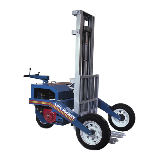
- Page 1 SERVICE/PARTS MANUAL MODELS: LJ100 Lift Jockey™ A 100% employee-owned American manufacturer REVISION: B 01/2002 PN 56489...
-
Page 3: Table Of Contents
Table of Contents Lift Jockey™ FOREWORD ........................... 4 LIMITED WARRANTY ......................... 5 TECHNICAL DATA ........................6 - 11 Specifications ..........................6 Machine Data/Lubrication Specifications .................. 7 Machine Sound Level ......................... 8 Operator Controls........................9 Imperial Torque Chart ......................... 10 Metric Torque Chart ........................11 Hardware Identification ...................... -
Page 4: Foreword
Battery Type: _______________________________ operation and the pertinent regulations for the prevention of accidents. Battery S/N: ________________________________ Stone Construction Equipment, Inc. is not Location of above information: liable for the function of the machine when used in an improper manner or for other 1. -
Page 5: Limited Warranty
No claim will be allowed for products lost or damaged in transit. Such claims should be filed with the carrier within fifteen days. Effective September 2001. Stone Construction Equipment, Inc. Phone: 1-800-888-9926 • 1-716-229-5141 Bred Tough, Technology Born To Work. -
Page 6: Technical Data
TECHNICAL DATA Specifications Stone Lift Jockey™ – Specifications Model LJ100 Base Weight (Kg) 750 (340) Mast Weight - 7’6" lbs (Kg) 400 lbs (182) - 8’6" lbs (Kg) 430 lbs (195) - 9’6" lbs (Kg) 475 lbs (215) Length (cm) 78"... -
Page 7: Machine Data/Lubrication Specifications
TECHNICAL DATA Machine Data Engine Type 8 hp 4-Stroke, Overhead Valve, Single Cylinder Engine Make Honda Engine Model GX240 Max Torque @ 2500 RPM 12.3 ft lb (16.8 Nm) Idle Speed 1400 RPM min Operating Speed 3400 RPM + 100 12 volt System Battery BCI Group U1-12 Battery 165 cca 5 amp Charge System... -
Page 8: Machine Sound Level
TECHNICAL DATA Machine Sound Level MACHINE SOUND LEVEL TEST Machine Type: Lift Jockey LJ100 Sound Level Meter Calibration Date: February 15, 2000 Meter Type: Simpson Model 886-2 Type 2 Test Date: October 31, 2001 Test Conditions Temperature: 50 degrees Fahrenheit / 10 degree Celsius... -
Page 9: Operator Controls
TECHNICAL DATA Operator Controls One-piece all welded steel frame pro- vides low center of gravity for maximum stability. Familiarization with locations and operation of controls is necessary before Direction Shift attempting to operate this vehicle. Steering Control Horn Button Air Cleaner Fuel Cap Up/Down Fuel Valve... -
Page 10: Imperial Torque Chart
TECHNICAL DATA Imperial Torque Chart SAE GRADE 5 SAE GRADE 8 Coarse Thread, Zinc-Plated Coarse Thread, Zinc-Plated SIZE TORQUE SIZE TORQUE ft. lbs. ft. lbs. 1/4 - 20 (.250) 1/4 - 20 (.250) 5/16 - 18 (.3125) 5/16 - 18 (.3125) 3/8 - 16 (.375) 3/8 - 16 (.375) 7/16 - 14 (.4375) -
Page 11: Metric Torque Chart
TECHNICAL DATA Metric Torque Chart Property Class 8.8 ZINC-PLATED Coarse Thread Fine Thread SIZE ft. lbs. ft. lbs. Property Class 10.9 ZINC-PLATED Coarse Thread Fine Thread SIZE ft. lbs. ft. lbs. 1000 Property Class 12.9 ZINC-PLATED Coarse Thread Fine Thread SIZE ft. -
Page 12: Hardware Identification
TECHNICAL DATA Hardware - 12 -... -
Page 13: Health & Safety
HEALTH & SAFETY Safety Precautions Before using this equipment, study this entire manual to When warning decals are destroyed or missing, contact become familiar with its operation. Do not allow the Manufacturer immediately at 1-800-888-9926 for untrained or unauthorized personnel, especially children, replacement. - Page 14 HEALTH & SAFETY Safety Precautions UNDERSTAND SIGNAL WORDS • A signal word – DANGER, WARNING, or CAUTION – is used with the safety-alert symbol. DANGER identifies the most serious hazards. • DANGER or WARNING safety signs are located near specific hazards.
- Page 15 HEALTH & SAFETY Safety Precautions • Never perform any work on the equipment while it is running. • Before working on the equipment, stop the engine and disconnect the spark plug wire(s) to prevent accidental starting. On electric models, disconnect the electric cord at the equipment. •...
- Page 16 HEALTH & SAFETY Safety Precautions Warning-Eye Protection • Always wear splash goggles when operating equipment. • Starting fluid (ether) is highly flammable, do not use or an explosion or fire may result. • Never operate unit in a poorly ventilated or enclosed area. •...
-
Page 17: Health & Safety
HEALTH & SAFETY Safety Precautions DISPOSE OF WASTE PROPERLY • Improperly disposing of waste can threaten the environment and ecology. Potentially harmful waste used with equipment include such items as oil, fuel, coolant, brake fluid, filters, and batteries. • Use leakproof containers when draining fluids. Do not use food or beverage containers that may mislead someone into drinking from them. -
Page 18: Maintenance
MAINTENANCE Tasks IMPORTANT The person attempting any of the following maintenance tasks must be authorized to do so and have read and understood all sections within this manual. - 18 -... -
Page 19: Introduction
Controls- Forward and reverse travel controlled by findings to Stone. We value our customer’s input rotating handle grips on steering tiller. All controls-- and welcome any and all comments on how the E-stop and horn, throttle, tilt control and lift/lower product may serve you better. -
Page 20: Fluids And Lubrication
MAINTENANCE Fluids/Lubrication FLUIDS AND LUBRICATION Engine Oil--SAE 30 API SH or SJ (oil with “starburst” certification mark) is recommended for Hydraulic Oil--Check the hydraulic fluid level. general, all temperature use. Check daily for proper Use the sight gage located on the hydraulic tank. oil level. - Page 21 MAINTENANCE Fluids/Lubrication Proper fuel storage is critically important. Use clean storage and transfer tanks. Periodically drain water WARNING and sediment from the bottom of the tank. Store fuel in a convenient place away from buildings. CLEAN UP SPILLED FUEL BEFORE STARTING AVOID FIRES BY KEEPING ENGINE CLEAN OF ACCUMULATED GREASE...
-
Page 22: Lubrication Points
MAINTENANCE Lubrication Points Lubrication Points--Refer to diagram below. Lube grease fittings with Lithium based grease • at steering column and drive axle every three (3) months or 50 hours. Use lube oil on the directional control pivots, • sheave, pins, lift chains and tilt cylinder pins with engine oil every 3 (three) months or 50 hours. -
Page 23: Engine
MAINTENANCE Engine SPARK PLUG ENGINE Recommended spark plug: Refer to engine manual for specific engine informa- BPR6ES (NGK) tion. W20EPR-U (NIPPONDENSO) To ensure proper engine operation, the spark plug ENGINE OIL AND FILTER must be properly gapped and free of deposits. •... -
Page 24: Cooling System
Battery warranty begins when equipment is sold shop manuals. from Stone Construction Equipment, Inc. or a Stone dealer to a customer. Battery--Battery replacement is a Crown U1-12 or equal 165 CCA battery. See Engine Specifications Battery warranty claims must include the unit’s... -
Page 25: Hydraulic Oil/Hydraulic Oil Filter
Hydraulic Oil/Hydraulic MAINTENANCE Oil Filter Mobil 424 SUS255/55CST ISO VG55 is recom- HYDRAULIC OIL mended for the hydraulic system. Do not mix hydraulic oils. Check oil level daily, replace The hydraulic drive motor is extremely reliable and hydraulic oil every 800 hours. will ordinarily not need maintenance or repair. -
Page 26: Hydraulic Breather Cap
Breather/Tires/Hardware MAINTENANCE Guideline/Hoses/Parking relieve all pressure. Before applying pressure to Hardware Guidelines system, be sure all connections are tight and lines, fittings and hoses are not damaged. Shear bolts are designed to fail under predetermined loads. Always replace shear bolts with identical HYDRAULIC BREATHER CAP grade. -
Page 27: Moving Without Power
Moving Without Power/ MAINTENANCE Cleaning and Storage • Latch is located just above the drive wheel at steering column Machine Cleanliness--Keep unit clean of all debris. • To lock handle, flip latch up to position against stop as indicated on decal •... -
Page 28: Periodic Maintenance Schedule
MAINTENANCE Periodic Maintenance Schedule - 28 -... -
Page 29: Periodic Maintenance Schedule
MAINTENANCE Periodic Maintenance Schedule - 29 -... -
Page 30: Service Record
MAINTENANCE Service Record Model No. Serial No. Record Hours and Dates of Maintenance Below Engine Oil and Filter (100 hours) Air Cleaner (300 hours) Spark Plugs (100 hours) Valves (300 hours) Hydraulic Oil (800 hours) Hydraulic Filter (100 hours) Hydraulic Breather (100 hours) Battery (monthly) -
Page 31: Troubleshooting
MAINTENANCE Troubleshooting 3UREOHP &DXVH 5HPHG\ Engine lacks power Fuel line plugged Clean or replace Dirty fuel filter Clean or replace Air filter dirty Clean or replace Worn cylinder & piston rings Replace Too much oil in crankcase Drain Oil consumption Worn valve guides Clean or replace Worn cylinder &... - Page 33 PARTS LIST Exploded Views with Parts Frame Assembly ......................34-35 Tilt Cylinder & Valve Assembly ..................36-37 Cowl Assembly ....................... 38-39 Front Wheel Assembly ....................40-41 Hydraulic Tank Assembly ....................42-43 Engine Assembly ......................44-45 Drive Axle & Steering Assembly..................46-47 Steering Handle Assembly ....................
-
Page 34: Frame Assembly
PARTS LIST Frame Assembly - 34 -... - Page 35 PARTS LIST Frame Assembly - 35 -...
-
Page 36: Tilt Cylinder & Valve Assembly
PARTS LIST Tilt Cylinder & Valve Assembly - 36 -... - Page 37 PARTS LIST Tilt Cylinder & Valve Assembly - 37 -...
-
Page 38: Cowl Assembly
PARTS LIST Cowl Assembly - 38 -... - Page 39 PARTS LIST Cowl Assembly - 39 -...
-
Page 40: Front Wheel Assembly
PARTS LIST Front Wheel Assembly - 40 -... - Page 41 PARTS LIST Front Wheel Assembly - 41 -...
-
Page 42: Hydraulic Tank Assembly
PARTS LIST Hydraulic Tank Assembly - 42 -... - Page 43 PARTS LIST Hydraulic Tank Assembly - 43 -...
-
Page 44: Engine Assembly
PARTS LIST Engine Assembly - 44 -... - Page 45 PARTS LIST Engine Assembly - 45 -...
-
Page 46: Drive Axle & Steering Assembly
PARTS LIST Drive Axle and Steering Assembly - 46 -... -
Page 47: Drive Axle & Steering Assembly
PARTS LIST Drive Axle and Steering Assembly - 47 -... -
Page 48: Steering Handle Assembly
PARTS LIST Steering Handle Assembly - 48 -... - Page 49 PARTS LIST Steering Handle Assembly - 49 -...
-
Page 50: Control Linkage Assembly
PARTS LIST Control Linkage Assembly - 50 -... - Page 51 PARTS LIST Control Linkage Assembly - 51 -...
-
Page 52: Mast Assembly
PARTS LIST Mast Assembly - 52 -... - Page 53 PARTS LIST Mast Assembly - 53 -...
- Page 54 PARTS LIST Mast Assembly - 54 -...
- Page 55 PARTS LIST Mast Assembly - 55 -...
-
Page 56: Lift Frame Assembly
PARTS LIST Lift Frame Assembly - 56 -... - Page 57 PARTS LIST Lift Frame Assembly - 57 -...
-
Page 58: Hydraulic Piping Schematic
PARTS LIST Hydraulic Piping Schematic - 58 -... - Page 59 PARTS LIST Hydraulic Piping Schematic - 59 -...
-
Page 60: Hydraulic System Schematic
PARTS LIST Hydraulic System Schematic - 60 -... - Page 61 PARTS LIST Hydraulic System Schematic - 61 -...
-
Page 62: Electrical Wiring Schematic
PARTS LIST Electrical Wiring Schematic - 62 -... - Page 63 PARTS LIST Electrical Wiring Schematic - 63 -...
-
Page 64: Decal Identification/Location
PARTS LIST Decal Identification 55398 - 64 -... - Page 65 PARTS LIST Decal Identification Item No. Part No. Part Description Decal Location 55269 Decal Fuel Shut Off 1 Top of Engine Fuel Tank 55398 Decal Warning Hot Surfaces 1 Rear Frame at Muffler 55422 Decal Hydraulic Fluid Mobil 424 1 Hydraulic Tank 55467 Decal Warning No Riders 1 Lift Cylinder Facing Forks...
- Page 66 PARTS LIST Decal Identification 55480 PARKING LATCH PROCEDURE THROTTLE HORN CONTROL SLOW FLIP LATCH TURN STEERING TO LOCK ARM ARM TO LEFT 55481 55479 FAST - 66 -...
- Page 67 PARTS LIST Decal Identification Item No. Part No. Part Description Decal Location 55269 Decal Fuel Shut Off 1 Top of Engine Fuel Tank 55398 Decal Warning Hot Surfaces 1 Rear Frame at Muffler 55422 Decal Hydraulic Fluid Mobil 424 1 Hydraulic Tank 55467 Decal Warning No Riders 1 Lift Cylinder Facing Forks...
-
Page 71: California Proposition 65 Warning
CALIFORNIA PROPOSITION 65 WARNING Operation of this equipment and/or engine exhaust from this product contains chemicals known to the State of California to cause cancer, birth defects, or other repro- ductive harm. - 71 -... - Page 72 The Way It Ought To Be. Stone Construction Equipment, Inc. P.O. Box 150, Honeoye, New York 14471 Phone: (800) 888-9926 Fax: 716-229-2363 e-mail: sceny@mcimail.com www: stone-equip.com A 100% employee-owned American manufacturer © 2001 Stone Construction Equipment, Inc. Printed in U.S.A.
Need help?
Do you have a question about the Lift Jockey LJ100 and is the answer not in the manual?
Questions and answers