Table of Contents
Advertisement
This document contains technology controlled for export by the U.S. Department of Commerce in
accordance with Export Administration Regulations. Diversion contrary to U.S. law prohibited.
COPYRIGHT © 2019
F
THALES DEFENSE & SECURITY, INC.
User Manual PN 84481 Rev 1
ALL RIGHTS RESERVED
Thales SureLINK IP Handset
User Guide
JULY 2019
JUNE 2017
JUNE 2017
JUNE 2017
i
Advertisement
Table of Contents

Summary of Contents for Thales SureLINK
- Page 1 JULY 2019 JUNE 2017 JUNE 2017 JUNE 2017 Thales SureLINK IP Handset User Guide This document contains technology controlled for export by the U.S. Department of Commerce in accordance with Export Administration Regulations. Diversion contrary to U.S. law prohibited. COPYRIGHT © 2019 THALES DEFENSE &...
- Page 2 RECORD OF CHANGES Date Description of Change Author Rev 1 July 2019 Initial Release SJacques WARNING – INFORMATION SUBJECT TO EXPORT CONTROL RESTRICTIONS WARNING – INFORMATION SUBJECT TO EXPORT CONTROL RESTRICTIONS WARNING – INFORMATION SUBJECT TO EXPORT CONTROL RESTRICTIONS WARNING – INFORMATION SUBJECT TO EXPORT CONTROL RESTRICTIONS This document contains technology controlled for export by the U.S.
- Page 3 Thales and others. No title to or ownership of any proprietary rights related to any Product is transferred to User or any Customer pursuant to the use of this product. The purchase of any Thales products shall not be deemed to grant either directly or by implication or otherwise, any license under copyrights, patents, or patent applications of Thales or any third party software providers, except for the normal, nonexclusive, royalty free license to use that arises by operation of law in the sale of a product.
-
Page 4: Table Of Contents
Table of Contents INTRODUCTION....................1-1 ......................... 1-1 NTRODUCTION SureLINK Key Features ....................... 1-1 Kit Contents ......................... 1-2 THALES SURELINK HANDSET BASICS ............ 2-1 LINK ..................2-1 ETTING TO NOW THE Thales SureLINK Interfaces ....................2-1 ........................2-3 NITIAL Installing the SureLINK Handset ..................2-3 Mounting the SureLINK Handset.................. - Page 5 List of Figures 1-1 T LINK H ............. 1-2 IGURE HALES ANDSET OMPONENTS 2-1 T LINK I ................2-1 IGURE HALES NTERFACES 2-2 E ............2-3 IGURE THERNET ABLE ONNECTION TO ANDSET 2-3 T LINK H TU /BDU ......... 2-4 IGURE HALES ANDSET...
- Page 6 SAFETY S HOCK HAZARD The Thales SureLINK Handset is a sealed system and is not meant to be opened for repair in the field by operators or technicians. Covers must WARNING remain in place at all times to maintain the warranty terms.
-
Page 7: Introduction
Make an emergency call with the onboard Emergency button, use the Thales Softphone application to make or receive phone calls discreetly or through the speakerphone, configure, and monitor the satellite system through the Thales Management Portal from the large touchscreen display. -
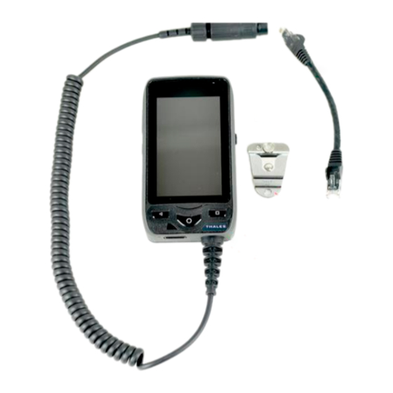
Page 8: Figure 1-1 Thales Surelink Handset Kit Components
Includes mounting hardware for mounting to a wall or hard surface Kit Contents The following list of equipment cones standard in the SureLINK kit and can be purchased individually as spares, depending on your requirements and/or needs. (Refer to Figure 1-1.) -
Page 9: Thales Surelink Handset Basics
THALES SURELINK HANDSET BASICS GETTING TO KNOW THE SURELINK Thales SureLINK Interfaces Figure 2-1 Thales SureLINK Interfaces Table 2-1 Interface Description Interface Description Touchscreen LCD Ruggedized gorilla glass display used to select the LINK icon and navigate through the screens. - Page 10 Interface Description Speaker Phone Audio Multiple audio ports used to project voice in all directions during Ports speaker phone calls 3.5mm Jack Allows a headset to be connected to the Handset. Standard headsets and earbuds should work through the 3.5mm jack. Speakerphone Microphone port on the side above the 3.5mm jack used during Microphone...
-
Page 11: Initial Set-Up
(TU) / Below Deck Unit (BDU). Figure 2-2 Ethernet Cable Connection to Handset 2. Once the SureLINK Handset is plugged in, the screen will power up. This may take a minute or so. The Handset is now ready to use. -
Page 12: Mounting The Surelink Handset
If mounting is desired, pre-drill and screw the mounting clip into a hard surface using the provided two screws. The button on the backside of the SureLINK Handset will securely fit into the clip for Handset storage while not in use. -
Page 13: Getting Started (Plug And Play)
Once the Handset is plugged into the TU / BDU and has powered up, it is ready for operation. (Note: the Handset does not have a ON/OFF BUTTON). 1. Press the center Android button to illuminate the screen. The Thales SureLINK home screen will appear (or it may automatically open the LINK app and display the Dial Pad). -
Page 14: Figure 2-5 Thales Handset Application Screen
4. When you first open the LINK Application (for the first time), the Dial Pad will be the first screen that appears. To enter the Handset Portal, press the PORTAL icon at the bottom left of the screen. Figure 2-6 Thales Handset Dial Pad Screen User Manual PN 84481 Rev 1... -
Page 15: Figure 2-7 Thales Link Portal
5. The LINK Application Dashboard will be displayed. The information contained in this screen is the same as you will see the TU / BDU Management Portal. Figure 2-7 Thales Link Portal For information pertaining to the Management Portal on the terminal unit, refer to either of the following user guides. -
Page 16: Figure 2-8 Settings (Main Screen)
6. The SETTINGS ICON ( ) allows you to configure the handset. Refer to Figures 2-8 and 2-9. Figure 2-8 Settings (Main Screen) Table 2-2 Settings (Main Screen) Section Parameters Device Display When selected, the user can: Adjust Brightness Level ... - Page 17 Section Parameters Device Language and Input When selected, the user can: Language – Set the desired language (English is the default setting) Keyboard and Input Methods – Keyboard type and Android keyboard settings System Time and Date When selected, the user can: ...
-
Page 18: Link Application Menu Components
Link Application Menu Components For information pertaining to the Management Portal on the terminal unit, refer to either of the following user guides. NOTE Thales MissionLINK ® User Manual (Document # 84468) Thales VesseLINK ™ User Manual (Document # 84469) - Page 19 Portal Tab Button– When selected, the Management Portal will come up. Note, this has the same menu components as you would see in the TU / BDU Management Portal. (Refer to Figure 2-7) Dial Tab Button – When selected, the phone key pad will be displayed. Telephone calls are made from this screen.
-
Page 20: Link Application - Settings
Link Application – Settings From the Link Application, the SETTINGS Button allows you to: Figure 2-10 LINK Application - Settings Table 2-4 LINK Application Settings Buttons Section Parameters Accounts Existing Account Provides information relating to an existing account already setup in the handset. Information includes: ... - Page 21 Section Parameters Audio Codecs Provides information relating to Mobile Data Audio Codecs and Wi-Fi Audio Codecs. (Information only) About About Displays current version information User Manual PN 84481 Rev 1...
-
Page 22: Operation
OPERATION SURELINK HANDSET OPERATION The Thales SureLINK Handset operates on an Android operating system that has been customized for the Handset operation. Many of the standard Android features and configuration items have been removed, as they are not applicable to the Handset operation. -
Page 23: Figure 3-1 Thales Handset Dial Pad Screen
Figure 3-1 Thales Handset Dial Pad Screen 2. Dial 9 first and then the number to be called and press Call. Once connected, if speakerphone mode is desired, follow instructions on the screen to first enable the keypad and then select speaker. You can also bring up the keypad, mute the Handset, put the call on hold or add a caller. -
Page 24: Receiving A Call
To change the volume, press and hold the volume button to increase volume and press and release sequentially to reduce the volume. NOTE To make a local call using the PBX, dial the extension you want to call (without the 9 first). NOTE Receiving a Call To receive a call from a caller over the satellite network, the caller would dial the Iridium... -
Page 25: Making An Emergency Call
Making an Emergency Call An Emergency Call can be made in two ways; either by selecting the Emergency Icon in the LINK Application or by pressing and holding the Emergency Button at the top of the Handset. Before either of these methods is used, the call number must first be configured. To do this: 1. -
Page 26: Figure 3-5 Enter The Emergency Number
Figure 3-5 Enter the Emergency Number 4. Exit by pressing either the Left Android button or the HOME button. Method 1 – Press and Hold the red Distress button on the top of the Handset. The Emergency Call sequence will initiate. A red CANCEL button appears on the screen with a 5-second countdown. -
Page 27: Management Portal
Figure 3-6 Emergency If no phone number has not been set up on the Handset but Emergency is enabled, the Distress call uses the email address that is set up in the Management Portal if one has been set-up. It NOTE also sends out the current location coordinates. -
Page 28: Technical Specifications
TECHNICAL SPECIFICATIONS TECHNICAL SPECIFICATIONS Table 4-1 Technical Specifications Category Technical Specification Operating Temperature -20°C to +55°C Regulatory FCC Part 15 Class B, EN61000-4 Humidity 95% at 40°C Audio Level (loud speaker) >90 db SPL Power Required POE < 6.5 watts 4”... - Page 29 THIS PAGE INTENTIONALLY LEFT BLANK User Manual PN 84481 Rev 1...
-
Page 30: Acronyms
ACRONYMS ACRONYMS Table 5-1 List of Acronyms Acronym Description Alternating Current Application Programming Interface Broadband Active Antenna Broadband Application Electronics Broadband Core Transceiver Built In Test Direct Current DHCP Dynamic Host Configuration Protocol DTMF Dual Tone Multi-Frequency Enhanced Broadband ETSI European Telecommunications Standards Institute GPIO General Purpose Inputs/Outputs... - Page 31 Smart Battery Charger Subscriber Identity Module Session Initiation Protocol SMBus System Management Bus Satellite Vehicle Transmission Control Protocol TDSI Thales Defense & Security, Inc. Transport Layer Security Terminal Unit User Datagram Protocol UL/DL Uplink/Downlink Voice Activity Detection VLAN Virtual Local Area Network...
- Page 33 User Manual PN 84481 Rev 1 Thales Defense & Security, Inc. 22605 Gateway Center Drive | Clarksburg MD 20871 Toll-Free 1.800.324.6089 | Phone: 240.864.7000 | Fax: 240.864.7920 Email: Customer.Service@thalesdsi.com | Website: www.thalesdsi.com...
Need help?
Do you have a question about the SureLINK and is the answer not in the manual?
Questions and answers