
Subscribe to Our Youtube Channel
Summary of Contents for BLUM MZR.5300.01
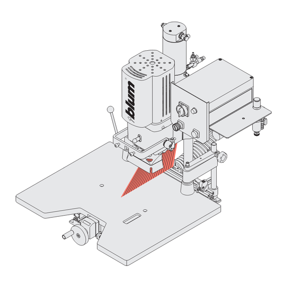
- Page 1 Laser module MZR.5300.01 Work steps should only be carried out by a licensed electrician! Please keep a copy of the operating instructions. BA-117/1EA MZR.5300.01...
-
Page 2: Table Of Contents
Contents A - Reading guide and safety instructions B - Technical Data C - Mechanical assembly of laser module D - Electrical connection of laser module E - Adjusting laser F - Troubleshooting G - Electrical circuit diagram BA-117/1EA MZR.5300.01... -
Page 3: A - Reading Guide And Safety Instructions
0 before starting work. • Follow all LOCKOUT / TAGOUT procedures established by management • Always use a voltage tester to ensure that components as well as control unit components are not energised before starting work. BA-117/1EA MZR.5300.01... - Page 4 Laser module MZR.5300 may only be used in combination with MINIPRESS P, MINIDRILL P in commercial and industrial applications. The manufacturer does not assume liability for uses not described in these operating instructions or the MINIPRESS P, MINIDRILL P operating instructions. BA-117/1EA MZR.5300.01...
-
Page 5: B - Technical Data
2.5 - 6 V DC • fan angle: 90° or 60° • Operating current: 30 mA • line thickness: 0.5 mm @ 250 mm • Operating temperature: -10 - 40 °C • Potential of housing: • Storage temperature: -40 - 80 °C BA-117/1EA MZR.5300.01... -
Page 6: C - Mechanical Assembly Of Laser Module
C.1 - Standard components • Wrench DIN EN 911 SW 2 mm • Wrench with “T“ handle DIN EN 911 SW 3 mm • Sub-assembly MZR.5300.01 • Power supply unit • 1 screw DIN 912 M 4x16 (ASTM F 912M:2004 ) •... - Page 7 • Insert mounting screw into the mounting hole on the backside of gearbox housing and rotate the screw 2 turns clockwise • Place the laser module on to the bolt slide to the right • Temporarily tighten the screw using the allen key provided BA-117/1EA MZR.5300.01...
-
Page 8: D - Electrical Connection Of Laser Module
The main switch does not disconnect the assembly machine from the air pressure system. D.2 - Retrofi tting the control unit • Remove the screws of the control unit housing using a scre- • Remove the control unit housing cover wdriver. • Turn the screws counter-clockwise BA-117/1EA MZR.5300.01... - Page 9 • Set aside enough remaining cable up to the cable tie • Mount the cable bushing • Thread the cable as shown • Attach cable along the pneumatic lines using the cable ties • Feed the cable through the cable bushing BA-117/1EA MZR.5300.01...
- Page 10 • Connect the laser diode to the low voltage side of the power • Replace the cover on the control unit housing supply unit • Turn the screws clockwise using a screwdriver • Put the label on the machine • Carry out the steps in chapter E BA-117/1EA MZR.5300.01...
-
Page 11: E - Adjusting Laser
E.2 - Check the laser angle • If laser angle is correct, all work steps are done. The machine with the laser module is ready for work. • If laser angle is wrong, carry out the steps in chapter F BA-117/1EA MZR.5300.01... -
Page 12: F - Troubleshooting
The laser beam is not perpendicular when it has moved from the zero position due to the stroke movement • Loosen set screw using allen key (counter-clockwise) • Move laser diode until the laser beam is perpendicular • Re-tighten set screw using allen key (clockwise) BA-117/1EA MZR.5300.01... - Page 13 T1,6A 690V IEC, 600V UL/CSA 4552380 250V, dm5x20mm, 1.6AT 1788700 250V/6A, G1/4" 3988890 230VAC 2456160 400V (max.690V), 12A 2456300 1,1kW, 220V/60Hz 3244009 220V~ 25µF, 400VDB 2649801 3,6V POTENTIOMETER 1x220V 60Hz S6-60%ED 7,3A, 1,1kW, 3325/min C 25µF 400VDB BA-117/1EA MZR.5300.01...
Need help?
Do you have a question about the MZR.5300.01 and is the answer not in the manual?
Questions and answers