
Subscribe to Our Youtube Channel
Related Manuals for McElroy TracStar 28


Summary of Contents for McElroy TracStar 28
- Page 1 Operator’s Manual TracStar ® No.28 TracStar ® No.412 TracStar ® No.618 Fusion Machines Patent No’s. 5,814,182 6,212,748 6,212,747 6,021,832 (other patents pending) Manual: T1210801 Revision: C 7/04...
- Page 2 California Proposition 65 Warning Engine exhaust from this product contains chemicals known to the State of California to cause cancer, birth defects, or other reproductive harm.
- Page 3 TX01853-9-27-00 (other patents pending) World Class Training McElroy Manufacturing, Inc., offers advanced training This manual is intended as a guide only and does not classes to enhance efficiency, productivity, safety and take the place of proper training by qualified instructors.
- Page 4 Claims cannot be allowed until the questioned product has been received, freight prepaid, at the manufacturer's McElroy Manufacturing, Inc. reserves the right to make factory, with complete information and data regarding any changes in or improvements on its products without the failure.
-
Page 5: Table Of Contents
Heater ..........2-7 COPYRIGHT © 2004 McELROY MANUFACTURING, INC. Tulsa, Oklahoma, USA All rights reserved All product names or trademarks are property of their respective owners. - Page 6 Table of Contents Operation Read Before Operating ........3-1 Check Oil Level .
- Page 7 Table of Contents Special Operations - Saddle Fusion Procedures - Continued Clamp Fitting ......... 5-3 Test for Slippage .
-
Page 8: Safety Alerts
Follow all applicable federal, state, local, and industry specific regulations. McElroy Manufacturing, Inc. cannot anticipate every possible circumstance that might involve a potential hazard. The warnings in this manual and on the machine are therefore not all inclusive. -
Page 9: General Safety
Fusion Equipment Safety General Safety Safety is important. Report anything unusual that you notice during set up or operation. LISTEN for thumps, bumps, rattles, squeals, air leaks, or unusual sounds. SMELL odors like burning insulation, hot metal, burning rubber, hot oil, or natural gas. FEEL any changes in the way the equipment operates. -
Page 10: Units With Engines
Fusion Equipment Safety Units With Engines Combustion engines can cause explosions when operated in a hazardous environment. Do not operate gas or diesel powered machines in a ¡PELIGRO! hazardous environment. When operating in a hazardous environment, keep engine and chassis in a safe area by using hydraulic extension hoses. Help prevent fires by keeping machine clean of accumulated trash, debris and facer shavings. -
Page 11: Battery
Fusion Equipment Safety Battery Do not expose the battery to flames or electrical sparks. Hydrogen gas generated by battery action is explosive. Blindness or serious injury can result from an exploding battery. Do not allow battery fluid to contact your skin, eyes, fabrics, or painted surfaces. -
Page 12: Crush Points
Fusion Equipment Safety Crush Points Hydraulically operated jaws are operated under pressure. Anything caught in the jaws will be crushed. Keep fingers, feet, arms, legs, and head out of the jaw area. Always check pipe alignment with a pencil or similar object. TX00103-4-6-93 Facer Blades Are Sharp Facer blades are sharp and can cut. -
Page 13: Keep Machine Away From Edge Of Ditch
Fusion Equipment Safety Keep Machine Away From Edge of Ditch Heavy equipment too close to a ditch can cause the walls of the ditch to cave-in. Keep the machine far enough away from the edge of the ditch to prevent injury to personnel and equipment from a cave-in. -
Page 14: Fusion Procedures
Fusion Equipment Safety Fusion Procedures Obtain a copy of the pipe manufacturer's procedures for the pipe being fused. Follow the procedure carefully, and adhere to all specified parameters. Failure to follow pipe manufacturer's procedure could result in a bad joint. Always follow pipe manufacturer's procedures. -
Page 15: Overview
Overview Theory of Heat Fusion The principle of heat fusion is to heat two surfaces to a designated temperature, and then fuse them together by application of force. This pressure causes flow of the melted materials, which causes mixing and thus fusion. When the polyethylene material is heated, the molecular structure is transformed from a crystalline state into an amorphous condition. -
Page 16: Carriage Assembly
Overview Carriage Assembly The carriage assembly consists of two fixed jaws and two hydraulically operated movable jaws bolted to the skid. For remote operation the carriage can be set in ditch and connected to the machine with optional hydraulic extension hoses.The carriage assembly (A) can be disconnected from the chassis (B) and removed for remote operation. -
Page 17: Gas Powered Units
Overview Gas Powered Units Read the operating and maintenance instructions for the engine before operating. The engine is a single cylinder, overhead valve, air cooled design. It uses a vacuum operated fuel pump. The fuel shutoff valve is located by the carburetor. TX01987-1-10-02 Tach and Hour Meter for Gas Unit When the unit is running, the engine speed is displayed. -
Page 18: Diesel & Gas Engine Controls
Overview Diesel Engine Controls Read the operating and maintenance instructions for the engine before operating. There is a key ignition on the console that shows the preheat off, run, and start positions. Gas Engine Controls Choke and throttle control is on the dash. There is a key ignition on the console that shows the off, run, and start positions. -
Page 19: Hydraulic Manifold Block
Overview Hydraulic Manifold Block Mounted on this block are a carriage directional control valve, a pressure reducing selector valve, three pressure reducing valves, and a 1500 psi gauge. A) The carriage control valve, mounted on the top of the manifold, determines whether the carriage is moving left, right, or is in neutral. -
Page 20: Facer
Overview Facer The facer is a McElroy Rotating Planer-Block design. The block rotates on a ball bearing and is chain driven by a hydraulic motor. When fusing 4” and 6” diameter pipe on the TracStar no.412 or No.618 move the facer blades to the inboard position. -
Page 21: Heater
Overview Heater This Heater Is Not Explosion Proof. Operation of heater in a hazardous environment without necessary safety precautions will result in ¡PELIGRO! explosion and death. The heater temperature is controlled by a microprocessor. It has a red indicator light on the handle at the bottom of the temperature scale. -
Page 22: Operation
Operation Read Before Operating Before operating this machine, please read this manual thoroughly and keep a copy available for future reference. Return manual to the protective storage box when not in use. This manual is to be considered part of your machine. TX00401-9-15-94 Check Oil Level Check oil level in the reservoir and verify that oil is visible in the... -
Page 23: Moving Machine Into Position
Operation Moving Machine Into Position Make sure all personnel are safely clear of the machine before moving. Stand behind the machine console. Move both track control levers forward to go in a straight line. Release the levers to stop. Moving just the right track forward turns the machine to the left. -
Page 24: Install Clamping Inserts
Operation Install Clamping Inserts Select and install appropriate clamping inserts for the pipe that is being fused. TX00368-9-15-94 Check Hydraulic Pressure The pressure gauge on the manifold block indicates the pressure at the carriage valve. How much pressure depends on the position of the selector valve and the pressure set on the specific pressure reducing valve. -
Page 25: Loading Pipe Into Machine
Operation Loading Pipe Into Machine Clean the inside and outside of pipe ends that are to be fused. Open the upper jaws and insert pipe in each pair of jaws with applicable inserts installed. Let the ends of the pipe protrude about 1"... -
Page 26: Remove Facer
Operation Remove Facer Swing the facer out to the storage position. Remove chips from pipe ends. Do not touch faced pipe ends. Inspect both pipe ends for complete face off. If the face off is incomplete, return to Loading Pipe into Machine. Move the carriage to the left until ends of pipe butt together. -
Page 27: Position Carriage For Heater Insertion
Operation Position Carriage for Heater Insertion Move carriage to the right to open a gap large enough to insert the heater. TX00374-9-15-94 Check Heater Temperature Incorrect heating temperature can result in questionable fusion joints. Check heater plates periodically with a pyrometer and make necessary adjustments. -
Page 28: Inserting Heater
Operation Inserting Heater Heater Is Not Explosion Proof. This unit is not explosion proof. Operation of heater in a hazardous environment without necessary safety ¡PELIGRO! precautions will result in explosion and death. If operating in a hazardous environment, heater should be brought up to temperature in a safe environment, then unplugged before entering the hazardous atmosphere for fusion. -
Page 29: Fusing The Pipe
Operation Fusing the Pipe Failure to follow pipe manufacturer's heating time, pressure, and cooling time may result in a bad joint. After following the pipe manufacturer's suggested heating procedure: A) Shift carriage control valve to neutral position. B) Shift the selector valve down to fusion position. C) Move the carriage to the right just enough to remove the heater. -
Page 30: Opening Fixed Jaws
Operation Opening Fixed Jaws Open the fixed jaws. TX00381-9-16-94 Raise Pipe Raise the joined pipe using the pipe lift. Push down on the pipe lift lever then release the latch. Pull the lever up to raise the pipe. TX00382-9-16-94 Hydraulic Pipe Lifts ®... -
Page 31: Position Pipe For Next Joint
Operation Position Pipe for Next Joint Drive the fusion machine to end of pipe, or pull the pipe through the jaws until the end of the pipe is protruding 1" past the jaw face of the fixed jaw. TX00383-9-15-94 Install Next Piece of Pipe Insert a new piece of pipe in movable jaws and repeat all previous procedures. -
Page 32: Special Operations - In Ditch
Special Operations - In Ditch Disconnect Hydraulic Hoses There are two sets of hydraulic hoses. One set connects to the carriage hoses on the machine and to the carriage. The other set connects to the facer hoses on the machine and to the facer. Disconnect both sets of hoses. -
Page 33: Remove 3-Jaw Assembly From The Carriage
Special Operations - In Ditch Remove 3-Jaw Assembly from the Carriage Remove braces from inner fixed jaw. Remove the four bolts holding carriage assembly to the chassis with the wrench provided. Attach lifting strap as shown and lift the carriage assembly. TX01875-11-8-00 4 - 2... -
Page 34: Remove Facer From Tracstar No.412 & No.618
Special Operations - In Ditch Remove Facer From TracStar No.412 and No.618 Machine Remove rear guide rod bracket. Remove facer locking bolts. Lift facer out of the carriage and set on cardboard or wood blocks off of ground. Attach rear guide rod bracket in the position shown. TX01992-1-10-02 4 - 3... -
Page 35: Remove Facer From Tracstar No.28
Special Operations - In Ditch Remove Facer From TracStar No.28 Machine Loosen facer locking bolt. Lift facer out of the carriage and set on cardboard or wood blocks off of ground. Remove rear guide rod bracket. Attach rear guide rod bracket in the position shown. TX01874-11-8-00 4 - 4... -
Page 36: Manual Facer Operation
Special Operations - In Ditch Manual Facer Operation Lift as shown. Lock onto back guide rod, then latch on front guide rod. TX01887-11-15-00 4 - 5... -
Page 37: Removing Top Jaws
Special Operations - In Ditch Removing Top Jaws If the carriage is going to be hand carried, or if the carriage needs to be hoisted and slid underneath the pipe, the top jaws need to be removed. Loosen all clamp knobs. Take out the detent pins securing the top jaws and remove the jaws. -
Page 38: Clamp Carriage Assembly To Pipe
Special Operations - In Ditch Clamp Carriage Assembly to Pipe Position carriage assembly on side of the pipe. Lift pipe and slide carriage assembly under pipe. Rotate carriage assembly around to a normal upright position. Attach the top jaws and loosely clamp around pipe. TX00879-2-19-96 4 - 7... -
Page 39: Attach Hydraulic Hoses
Special Operations - In Ditch Attach Hydraulic Hoses There are two sets of hydraulic extension hoses. One set connects to the carriage hoses on the machine and to the carriage. The other set connects to the facer hoses on the machine and to the facer. -
Page 40: Special Operations - Saddle Fusion Procedures
Special Operations - Saddle Fusion Procedure Saddle Fusion Procedure for TracStar No.28CU The combination unit is capable of saddle fusing up to an 8" (200 mm) branch on any size main. TX00454-9-22-94 Install Heater Adapters Heater is Not Explosion Proof. Operation of heater in a hazardous environment without necessary safety precautions will result in explosion and death. -
Page 41: Install Clamping Inserts
Special Operations Saddle Fusion Procedure Install Clamping Inserts Select and install appropriate clamping inserts in the movable jaw(s). TX00457-9-16-94 Remove Carriage Assembly from Vehicle Use lifting sling and detach carriage from vehicle. Refer to pg. 4-1 TX01880-11-10-00 Attach Carriage Assembly to Main Place the machine on the main. -
Page 42: Clean Surfaces
Special Operations - Saddle Fusion Procedure Clean Surfaces Use 50 or 60 grit utility cloth to clean and rough the main to expose fresh material. Rough the base of the fitting unless the manufacturer specifies otherwise. Surface must be free of water and oil. TX01879-11-10-00 Clamp Fitting Position the fitting, and bolster if required, loosely in the movable... -
Page 43: Prepare Heater
Special Operations - Saddle Fusion Procedure Prepare Heater Heater is Not Explosion Proof. Operation of heater in a hazardous environment without necessary safety precautions will result in explosion and death. If operating in a hazardous environment, heater should be brought up to temperature in a safe environment, then unplugged before entering the hazardous atmosphere for fusion. -
Page 44: Fuse Fitting To Pipe
Special Operations - Saddle Fusion Procedure Fuse Fitting to Pipe Remove the heater with a snap action and quickly inspect the melt pattern. Quickly move the carriage to the right bringing the fitting and main together under the pipe manufacturer's recommended pressure. -
Page 45: Heavy Overhead Load
Special Operations - Lifting Fusion Machine Heavy Overhead Load Fusion machine and plastic pipe are heavy. If loaded or lifted improperly, they could crush or kill. Handle load carefully with proper overhead ¡PELIGRO! rigging and equipment of adequate load rating. TX00062-3-8-93 Crush Points Crush points exist on this machine. -
Page 46: Attach Slings
Special Operations - Lifting Fusion Machine Attach Slings Attach the sling to the pick-up points. The cables are color coded to the chassis. Connect the yellow cables to the yellow lift points, etc. For machines that are not color coded, attach the longest leg cable at position A and the shortest leg cable at position B. -
Page 47: Maintenance
Maintenance Preventative Maintenance To insure optimum performance, the machine must be kept clean and well maintained. With reasonable care, this machine will give years of service. Therefore, it is important that a regular schedule of preventive maintenance be kept. Store machine inside, out of the weather, whenever possible. TX00428-8-10-95 Washing the Machine The machine should be cleaned, as needed with a soap and... -
Page 48: Install/Remove Covers
Maintenance Install/Remove Covers Hook top of cowl on three clips. Align the thumbscrew in the socket and tighten. Align the rear latches and fasten the latch, making sure it locks. The cowl should be outside the dash panel Align and fasten the front latch the same way. Reverse the procedure to remove the cowls. -
Page 49: Engine Belt Tension Adjustment
Maintenance Engine Belt Tension Adjustment Check the engine belt tension every 100 hours of operation. A force of 7lb. should deflect the belt 1/8 inch. If oil has gotten on the belt it will need to be replaced. TX01996-1-10-02 Tensioning the Belt The tensioner is located beside the rear pipe lift. -
Page 50: Engine Oil System - Diesel
Maintenance Engine Oil System - Diesel Change engine oil and filter after the first 50 hours of operation. After the first oil change, change the oil and filter every 200 hours of operation. Read the engine maintenance instructions. Use appropriate single weight oil for the ambient temperature. The oil filter is located behind the engine access panel. -
Page 51: Check Gauge Calibration
Maintenance Check Gauge Calibration Gauge calibration should be checked daily. The gauge should read zero when the unit is not running. Damaged gauges should be replaced. TX00432-9-13-94 Clean Jaws and Inserts To prevent slippage and insure proper alignment, the jaws and inserts must be clean. -
Page 52: Clean The Clamping Chains
Maintenance Clean the Clamping Chains On the combination unit clean the side fusion chains as needed. Clean using a stiff-bristled brush and oil generously. Wipe away any excess oil. TX00436-9-13-94 Fasteners Must Be Tight Check all nuts, bolts, and snap rings to make certain they are secure and in place. -
Page 53: Clean Heater Surfaces
Maintenance Clean Heater Surfaces The heater faces must be kept clean and free of any plastic build up or contamination. Before and after each fusion joint the heater surfaces must be wiped with a clean, non-synthetic cloth. NOTICE: Do not use an abrasive pad or steel wool. Use a non- synthetic cloth that won't damage surfaces. -
Page 54: Installing Butt Fusion Heater Adapter
If the heater is not operating properly, the control will attempt to turn the heater off and the indicator light will flash rapidly. If this occurs, disconnect the power and take it to a McElroy Authorized Service Center for repair. -
Page 55: Engine Maintenance
Maintenance Engine Maintenance Refer to the operation and maintenance manual for the engine. TX01500-3-5-98 Checking Track Tension Park the machine on a flat solid surface. Use the lifting sling to raise machine off the ground. Place adequate supports under the the bottom frame after lifting. Measure the deflection between the bottom center roller and the inside surface of the rubber track. -
Page 56: Adjusting Track Tension
Maintenance Adjusting Track Tension The grease in the hydraulics of the track is pressurized. If the grease valve is loosened too much, grease can be expelled at high pressure and cause serious injury. Never loosen grease valve more than one turn. Injury could also result if the grease nipple is loosened. -
Page 57: Machine Checklist
Maintenance Checklist Fusion Machine Checklist Items to Check Satisfactory Needs Repair Comments Repair UNIT Machine is clean All pins and snaprings are in place All nuts and bolts are tight All identification placards and handles are in place All clamp knobs are lubricated and turn freely Wiring, battery cables, &... -
Page 58: Determining Fusion Pressure
Determining Fusion Pressure Variable Definitions O.D. = Outside Diameter = Wall Thickness ∏ = 3.1416 = Standard Dimensional Ratio = Manufacturer’s Recommended Interfacial Pressure TEPA = Total Effective Piston Area Formulas O.D. t = ------------ AREA = (O.D. - t) x t x ∏ FORCE = AREA x IFP (O.D. -
Page 59: Hydraulic Fluid
Hydraulic Fluids Hydraulic Fluids The use of proper hydraulic oil is mandatory to achieve maximum performance and machine life. Use a clean, high quality, anti-wear hydraulic oil with a viscosity index (VI) of 135 minimum. It should have a maximum viscosity of 500 cSt (2000 SSU) at startup (ambient temperature) and a minimum viscosity of 13 cSt (65 SSU) at the maximum oil temperature (generally 80°F above ambient). -
Page 60: Specifications
Specifications ® TracStar No.28 Fusion Machine Specifications: 44'' 1118mm Engine: 11HP, OHV, Air Cooled 30'' 762mm Starting System: Electric and Recoil Fuel Type: Gasoline 1000 DIRECTIONAL CONTROL VALVE 47.4'' SELECTOR FACING PRESSURE VALVE HEATING Fuel Tank Capacity: 5 Gals. PRESSURE FUSING PRESSURE 1204mm... -
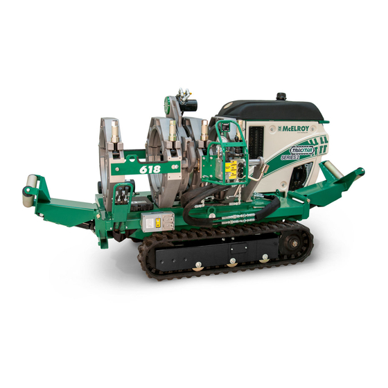
Page 61: Tracstar ® No.618Fusion Machine Specifications
Specifications ® TracStar No.618 Fusion Machine Specifications: 44'' 1118mm 30'' Engine: 18.5 HP Liquid Cooled 762mm Starting System: Electric Fuel Type: Diesel 50.4'' Fuel Tank Capacity: 5 Gals. 1280mm Operational Tank Capacity: 8 Hrs. System Pressure: 2000 PSI 42.5'' Hydraulic Reservoir Capacity: 8 Gals 1080mm Vehicle Speed: 1.5 MPH 98.5''... - Page 62 About this manual . . . McElroy Manufacturing continually strives to give customers the best quality products available. This manual is printed with materials made for durable applications and harsh environments. This manual is waterproof, tear resistant, grease resistant, abrasion resistant and the bonding quality of the printing ensures a readable, durable product.
Need help?
Do you have a question about the TracStar 28 and is the answer not in the manual?
Questions and answers