Advertisement
Quick Links
INSTALLATION INFORMATION
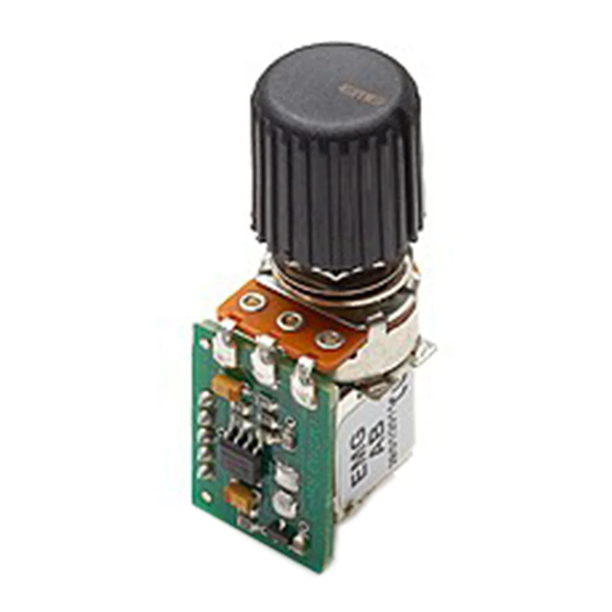
EMG MODEL: AB (AFTERBURNER)
(ACTIVE/PASSIVE PICKUP INPUTS)
SPECIFICATIONS
Input Impedance (Ohms)
Input Referred Noise
Output Impedance (Ohms)
Current @ 9V (Microamps)
Battery Life (Hours)
Maximum Supply (Volts DC)
GENERAL OPERATION:
The EMG-AB is a booster pre-amp that uses a Push-Pull Pot to activate the amount of boost you want. When the Push-Pull pot is in the "down"
position there is no boost and the control has no effect. In the "up" position, rotating the pot can boost the input by up to 20dB at full rotation.
Both passive and active pickups can be used with the EMG-AB. The AB is designed to be placed last in the signal chain just before the output jack.
Also, the AB will convert a guitar with passive (High Impedance) pickups to a low impedance output.
A few notes about boosting:
The amount of "clean" boost you can get from the AB is dependent upon the amount of gain you set on the pot and the level of power
supply you have. The usual supply is 9 Volts. If you turn the pot for maximum boost (20dB) the maximum input is .70 Volts for a clean output
when supplied with a 9 Volt battery. If you turn the pot 1/2 way (10dB) the maximum input will be 1.4 Volts input for a clean output.
By increasing the power supply to 18 Volts, you can virtually double the "clean" headroom of the AB.
As the battery voltage begins to drop from use, the amount of "Clean" headroom will diminish as well. If you want a clean boost, then replace
your battery fairly often., or operate at 18 Volts to maximize headroom. If you don't care about how clean the signal is, but just want to blow
your mind, don't worry about the supply voltage until you don't get the sound you're looking for then change the battery or... Just... Rock on!
IMPORTANT INSTALLATION NOTES:
Only one 9-Volt battery is required to power the pickups and any accessories such as the AB, SPC, EXG or other EMG Controls.
Use an Alkaline or Lithium battery for longest life. If your installation is different from the diagrams in these instructions or you need additional
diagrams visit our website: emgpickups.com for a complete listing of available diagrams.
Dimensions:
.400
(10)
1.910
(48.5)
1.160
(29.5)
.700
(17.8)
Warranty
All EMG Pickups and accessories are warranted for a period of two years. This warranty does not cover failure due to improper installation, abuse or damage. If
upon examination the pickup is determined to be defective, a replacement will be made. Warranty replacement products are covered by this same warranty. This
warranty covers only those pickups and accessories sold by authorized EMG Dealers. This warranty is not transferable.
© 2010 Copyright EMG INC. All Rights Reserved.
250K
-130dbV
2K
980
250
18
.740
(19)
INPUT
GROUND
GROUND
OUTPUT
V++
.810
(16.6)
AB
(AFTER-BURNER)
INCLUDED:
1 AB Control
1 Battery Clip with Buss Connector
1 Stereo Output Jack (Battery Switching)
3 Interconnect cables
.309 (8mm P .75)
Connector for EMG Active Tone controls
and accessories.
Pin 1
Input
Pin 2
Ground for Input
Pin 3
Ground for Output
Pin 4
Output
Pin 5
V+ Supply
Advertisement

Related Manuals for EMG AB

Summary of Contents for EMG AB
- Page 1 In the “up” position, rotating the pot can boost the input by up to 20dB at full rotation. Both passive and active pickups can be used with the EMG-AB. The AB is designed to be placed last in the signal chain just before the output jack.
- Page 2 Keep in mind that all of the EMG Accessory controls can be substituted for one another since they all have buffered inputs and utilize the same 5-pin connnector. So, if you decide you would like to use an EXG rather than the AB, simply unplug Input the AB and replace it with the EXG.
- Page 3 2 Pickup Guitars using a selection switch: Diagrams #4 and #5 show the pickups connected to the B157 Pickup Buss. To learn more about the B157 Pickup Buss, be sure to go to the EMG Website: http://www.emgpickups.com. More diagrams are available at the EMG website.
- Page 4 Be sure to reverse the connector on the input of the VLPF as shown. 3) Plug a coax cable from the output of the VLPF to the input of the AB Control. 4) Plug the output cable from the AB Control to the output jack.
Need help?
Do you have a question about the AB and is the answer not in the manual?
Questions and answers