
Related Manuals for Chevin Research A Series


Summary of Contents for Chevin Research A Series
- Page 1 USER MANUAL A Series Professional Power Amplifiers Minimum 4 ohm Minimum 2 ohm A500 A2000 A700v A3000 A750 A4000 A1000 A5000 A1004 A5003 A1500 A6000 Q900 Q1004 QB1000/600...
-
Page 2: Installation
IF ANY ITEM IS MISSING OR DAMAGED, CONTACT YOUR DEALER IMMEDIATELY. COOLING & A Series amplifiers draw in air at the back and expel it at the front: keep front & back of unit free of obstruction. ENVIRONMENTAL The amplifier may be used free-standing or installed in a 19" rack. If installed in a rack, the rear of the chassis should be supported. - Page 3 INSTALLATION OUTPUT Connection is made to the amplifier's load via Neutrik Speakon sockets. As with input CONNECTIONS connectors, maintain phase polarity throughout the system. Speakon A500 1 Speakon socket per channel, wired as follows: Socket Wiring 1+ = HOT 2+ = NO CONNECTION 1- = GROUND 2- = GROUND A700v...
-
Page 4: Operation
- disconnect the amplifier from the mains and consult a qualified engineer. WARNING Chevin Research accepts no responsibility or liability relating to injury or damages suffered as a result of misuse or unauthorised tampering with any of its amplifiers... -
Page 5: Mono Bridge Mode
MONO BRIDGE MODE WARNING: YOU CANNOT BRIDGE THE A700v, A5000 (4U), A6000 or QB1000/600 A500 INPUT CONNECTIONS Make a lead with a suitable connector for the source equipment and two (2) XLR plugs for the amplifier end. The HOT output from the source equipment goes to Pin 2 of Ch. A XLR plug and Pin 3 of Ch. B XLR plug The COLD connection from the source equipment goes to Pin 3 of Ch A. -
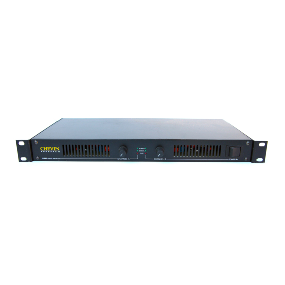
Page 6: Front Panels
FRONT PANELS A500 A700V A750, A1000, A1004, A1500, A2000, A3000 A4000, A5003... - Page 7 Q1004, QB1000/600 Q900 1. Power Switch Controls the mains power supply to the amplifier 2. Output Controls Controls the output level (gain) of each channel 3. Power LEDs Top green LEDs. They illuminate when the unit is ON 4. Clip LEDs Red LEDs, one per channel.
-
Page 8: Back Panels
BACK PANELS A500 A700V A750, A1000, A1004, A1500, A2000, A3000 QB1000/600 Q1004... - Page 9 A4000 A5003 Q900 A5000/A6000 1. Vari Speed Fans On the A500 & A700V, the fan is internal. On all other models, fans are at the back. These spin at variable speeds depending on the signal level and ambient temperature 2. Mains Input On the A500 &...
-
Page 10: Specifications
SPECIFICATIONS A500 A1000 A1004 A1500 Q1004 QB1000/600 Specifications RMS Power Output into 4Ω, watts per channel 1000 1250 1000 2 x 1000/ 2 x 600 into 8Ω, watts per chanel 2 x 600 / 2 x 375 No of Channels 2Hz-80kHz 2Hz-80kHz Power Bandwidth +0dB, - 3dB... - Page 11 SPECIFICATIONS A6000 Specifications A2000 A3000 A4000 A5003 R R M M S S P P o o w w e e r r O O u u t t p p u u t t 10Hz-20kHz into 2Ω, watts per channel 3000 watts 1200 watts 1600 watts...
- Page 12 Failure to register by not returning the warranty card in no way limits or invalidates the warranty, but in the event of service being required, delay may result since warranty work cannot begin until thje original sale has been verified. In case of difficulty, contact CHEVIN RESEARCH LTD. This warranty in no way affects your statutory rights. Head Office: Chevin Research Ltd., 41a IIkley Road, Otley, West Yorkshire LS21 3LP ENGLAND...
Need help?
Do you have a question about the A Series and is the answer not in the manual?
Questions and answers