Table of Contents
Advertisement
Quick Links
Model : ACEWT86260
Foreword
This manual applies to 1310nm AM direct modulated optical transmitter with SNMP network management
interface. It mainly describes the performance characteristics, technical parameters, installation and debugging,
common troubleshooting, and other related content of the product. In order to ensure that the equipment can be
successfully installed and safely operated, please read this manual carefully before installing and debugging
the equipment. And the installation and debugging should be strictly according to the specified steps on the
manual to avoid unnecessary damage to equipment or accident harm to the operator. Any question, please
contact with us in time.
Special Tips:
n Optical transmitter is professional equipment, and its installation and debugging must be operated
by special technician. Read this manual carefully before operating to avoid damage to equipment
caused by fault operation or accident harm to the operator.
n While the optical transmitter is working, there is an invisible laser beam from the optical output adapter
on the front panel. Avoiding permanent harm to the body and eye, the optical output should not aim at
the human body and human should not look directly at the optical output with the naked eye!
n Please make sure that the ground terminal of the case and power outlet has been reliably grounding.
Before turning on the power (Grounding resistance should be less than 4
damage the pump laser device and harm to human because of case charged.
n To ensure the equipment can work stable over a long time in voltage unsteady or poor voltage wave
region, it's recommend to the customer that he equips special AC regulated power supply, or even
AC uninterrupted power supply(UPS)system for conditional region. In the region with large temperature
variation environment (The equipment's ideal work environment temperature is 25°C) or bad room
environment it's recommend to the customer that he equips special air-condition system to improve
the work environment.
Fiber Optic
ACEWT86260
TX-1310
Ω
) to prevent the static
Advertisement
Table of Contents

Summary of Contents for HSTN ACEWT86260
- Page 1 Fiber Optic Model : ACEWT86260 ACEWT86260 TX-1310 Foreword This manual applies to 1310nm AM direct modulated optical transmitter with SNMP network management interface. It mainly describes the performance characteristics, technical parameters, installation and debugging, common troubleshooting, and other related content of the product. In order to ensure that the equipment can be successfully installed and safely operated, please read this manual carefully before installing and debugging the equipment.
-
Page 2: Product Summary
Fiber Optic Model : ACEWT86260 ACEWT86260 TX-1310 1. Product Summary Optical transmitter is the most important equipment to construct the CATV HFC network. It mainly used for the long distance optical fiber transmission of TV image signal, digital television signal, telephone voice signal and data (or compressed data) signal. -
Page 3: Block Diagram
Fiber Optic Model : ACEWT86260 ACEWT86260 TX-1310 3. Block Diagram 4. Technology Parameters 4.1 Link test condition Special instruction : The performance of this manual according to the measuring method of GY/T 143-2000 <Specification and methods of measurement on AM optical transmitter and receiver used in CATV system>,and tested under the specified test condition. - Page 4 Fiber Optic Model : ACEWT86260 ACEWT86260 TX-1310 Input return loss ≥ 16 ( 47-550MHz ); ≥ 14 ( 550-750/862/1003MHz ) C/CSO ≥ 60 C/CTB ≥ 65 ≥ 51 AGC control range ±5 MGC control range 0-10 Power supply voltage AC 110V-250V (50Hz)
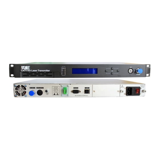
- Page 5 Fiber Optic Model : ACEWT86260 ACEWT86260 TX-1310 5. External Function Description 5.1 Front Panel Description 1) Power indicator: The light is on while the switching power supply inside is working. 2) Device running indicator: This indicator will flash after the device start running.
- Page 6 Fiber Optic Model : ACEWT86260 ACEWT86260 TX-1310 RF Channel Number : RF control mode at present Input RF : 30.7 dB µ RF Control Mode: Input RF : 30.5 dB µ The offset of control level in the AGC RF Control Mode:...
-
Page 7: Setting Menu
Fiber Optic Model : ACEWT86260 ACEWT86260 TX-1310 6) Setting menu 1.Disp Parameters 2.Set Parameters…………………….. 3.Alarm Status Pass “Enter” key into the menu Content Meaning Set Laser Output Unit……… Set the displayed optical power unit Set Buzzer Alarm Set RF Control Mode... -
Page 8: Installation Steps
Fiber Optic Model : ACEWT86260 ACEWT86260 TX-1310 6. Installation debugging 6.1 Unpack and Check 1. Insure the package is not defaced. If it has any damage or water mark, please contact local agency or carrier. 2. After unpacking, check equipment and accessories according to package list. Any question, please contact local agency or our company. - Page 9 Fiber Optic Model : ACEWT86260 ACEWT86260 TX-1310 7. Common Failure Analysis and Troubleshooting Failure phenomenon Failure cause Solution Check if the power supply is normal (should be AC: 110V-250V). If the Power on, the front panel Switch powering power supply couldn’t...
- Page 10 Fiber Optic Model : ACEWT86260 ACEWT86260 TX-1310 1. Check if there is a strong interference signal source; change the optical contact point location if possible to avoid the influence of strong interference signal sources. 2. Check the cable lines before the...
-
Page 11: Special Notice
Fiber Optic Model : ACEWT86260 ACEWT86260 TX-1310 The Clean and Maintenance Method of Optical Fiber Connector In many times, we consider the decline of the optical power as the equipment faults, but actually it may be caused by that the optical fiber connector was polluted by dust or dirt. Inspect the fiber connector, component, or bulkhead with a fiberscope.
Need help?
Do you have a question about the ACEWT86260 and is the answer not in the manual?
Questions and answers