Table of Contents
Advertisement
Advertisement
Table of Contents

Summary of Contents for New Focus 3501
- Page 1 Artisan Technology Group is your source for quality new and certified-used/pre-owned equipment SERVICE CENTER REPAIRS WE BUY USED EQUIPMENT • FAST SHIPPING AND DELIVERY Experienced engineers and technicians on staff Sell your excess, underutilized, and idle used equipment at our full-service, in-house repair center We also offer credit for buy-backs and trade-ins •...
- Page 2 Model 3501 User’s Manual Optical Chopper Artisan Technology Group - Quality Instrumentation ... Guaranteed | (888) 88-SOURCE | www.artisantg.com...
-
Page 3: Table Of Contents
Quick Start Operation Rack Mount Kit VII Computer Control VIII Command Summary Troubleshooting AC Operating Voltages Specifications Is a registered trademark of 351007 Rev. B New Focus, Inc. Artisan Technology Group - Quality Instrumentation ... Guaranteed | (888) 88-SOURCE | www.artisantg.com... -
Page 4: Warranty
Warranty New Focus, Inc. guarantees the chopper head to be free of defects for 90 days from the date of shipment. All other parts of the Model 3501 Optical Chopper are guaranteed to be free of defects for one year from the date of shipment. -
Page 5: Introduction
Introduction The Model 3501 Optical Chopper is designed to interrupt light paths in optical experiments at frequencies from 4 Hz to 6.4 kHz. Both single and dual beam experiments can be performed across a broad range of chopping frequencies. The chopper has a crystal controlled frequency synthesizer that serves as an internal reference frequency for locking the chopper to a particular chopping frequency. - Page 6 The chopper head can be mounted on a 1/2”-diameter post or bolted directly to a standard optical bench. The Model 3501 Optical Chopper is supplied with four chopper wheels and a wheel cover. The Model 3510 Rack Mount Kit, an accessory that is sold separately, enables the chopper controller to be mounted in a rack (see Page 21).
-
Page 7: Safety And
Use Mounting the Chopper Head The Model 3501 Optical Chopper head may be secured to standard optical benches using 1/4-20 or M6 bolts. The bolts pass through the mounting plate perpendicular to the plane of the optical bench. The chopper head can be rotated off-axis by loosening the 1/4-20 set screws on the side of the motor mount. - Page 8 Environment The Model 3501 Optical Chopper may be operated in an ambient of 0 to 40 degrees C. It is recommended to avoid direct sunlight on the LED display. WARNING: Hazardous voltages, capable of causing death, are present inside this instrument.
-
Page 9: Quick Start
Quick Start Before operating the Model 3501 Optical Chopper, please review the previous section to make sure the chopper is ready for use. 1. Mount the chopper head securely on an optical bench. 2. Mount the 42/30 wheel on the head. Avoid bending the wheel. The wheel should be free to turn without contact to the optical sensor or nearby equipment. -
Page 10: Operation
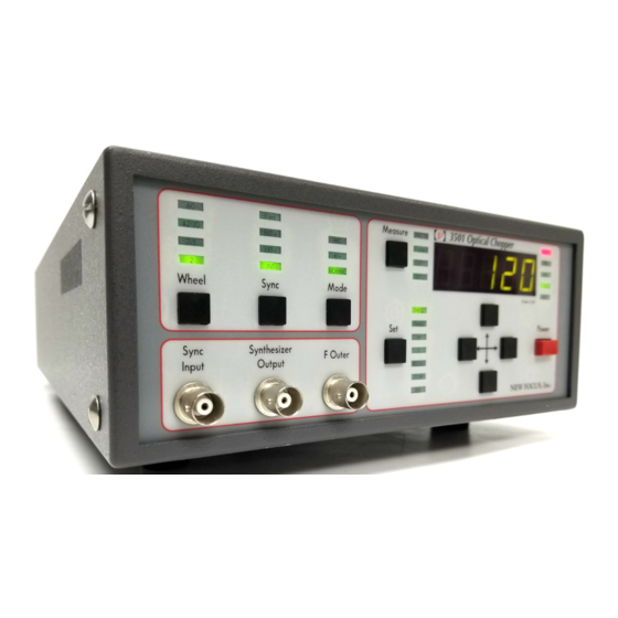
Made in USA FREQ PHASE Power Sync Synthesizer F Outer Input Output RECALL STORE IEEE NEW FOCUS, Inc. Fig. 2 Front panel of the Model 3501 chopper controller. Artisan Technology Group - Quality Instrumentation ... Guaranteed | (888) 88-SOURCE | www.artisantg.com... - Page 11 Wheel Front Panel Operation The user may select from single or double slot wheels to perform single or dual path experiments. Different wheel apertures may be selected to accom- modate the chopping frequency of interest. The table below summarizes wheel choices and chopping frequency ranges. Wheel Type Lowest Frequency Highest Frequency (slots)
- Page 12 Mode The Mode setting changes the reference signals available at OUT1 and OUT2 on the back panel as follows: Mode F outer OUT1 OUT2 [H/S]·F sync [H/S]·F sync [H/(7·S)]·F sync F sync F outer - F inner F outer + F inner NORMAL F sync 5·F outer...
- Page 13 When INT Sync is selected, the synthesizer frequency will be restricted to the working range of the particular chopping wheel. In H/S mode this range will be modified by the setting of H and S. In this case, the range limits may be calculated as follows: F upper = F outer [highest] ·...
- Page 14 42/30 wheel, internal sync, normal mode, 84 Hz, IEEE address 12. IEEE The user may select the Model 3501’s device address on the IEEE-488 bus. The factory default setting is 12. Use the up arrow or down arrow key to change the device address.
- Page 15 To change the Measure parameter, press the Measure key until the LED lights under the desired parameter. Sync Input The user may connect a TTL level sync frequency at the Sync Input. EXT+ or EXT- sync must be selected and the frequency must remain within the limits defined above in the FREQ section.
- Page 16 Back Panel Operation OUT1 The function of the OUT1 output depends on the instrument’s operating mode. In H/S mode, the instrument provides a TTL level pulse at fre- quency [H/S]·F sync . In +/- mode the frequency at OUT1 is F outer - F inner , and in NORMAL mode the frequency is 5·F outer .
- Page 17 V ext When V ext sync is selected, the user may drive the chopper motor directly with a DC input voltage. 0 to -10 V DC corresponds to 0 to 100% of the highest motor speed. MOTOR Use the supplied cable to connect the chopping head to the chopper controller at the back panel.
- Page 18 Chopper Head Cable The cable that connects the control unit to the chopper head is a six conduc- tor reverse RJ11 type IDC telephone cable. Connect the cable from the connec- tor on the side of the chopper head to the MOTOR connector on the back panel of the control unit.
- Page 19 Mounting the Chopper Head The Model 3501 Optical Chopper head may be secured to standard optical benches using 1/4-20 or M6 bolts. The bolts pass through the mounting plate perpendicular to the plane of the optical bench. This mounting method pro- vides the advantage of allowing the wheel to be rotated off-axis by loosening the 1/4-20 set screws on the side of the motor mount.
- Page 20 Diameter 4.50" (114.3 mm) 2 Slot 7/5 Slot 42/30 Slot 60 Slot Fig. 5 The four chopper wheels that are supplied with the chopper. Artisan Technology Group - Quality Instrumentation ... Guaranteed | (888) 88-SOURCE | www.artisantg.com...
- Page 21 Wheel Cover The wheel cover attaches to the chopper head with 4 screws. The wheel cover is made of .030” aluminum with an anti-reflective black anodized coating. Two concentric slots, etched in both faces of the cover, allow apertures up to .3 and .4-inches wide over most of the chopping wheel surface.
-
Page 22: Rack Mount Kit
The Model 3510 Rack Mount Kit is a chopper accessory (not supplied with the Mount Kit Model 3501 Optical Chopper) that allows one or two chopper controllers to be mounted in a standard rack. The kit consists of 2 short ears, 1 long ear, 1 rack plate, and 6 6-32 flathead screws. - Page 23 Computer Control The Model 3501 Optical Chopper may be programmed remotely by IEEE-488 interface. The Model 3501 supports the IEEE-488.1 (1978) interface standard, and any computer that supports this interface may be used. A total of fifteen commands are available that enable any front panel operation to be per- formed remotely.
- Page 24 Model 3501. The suffix “?” indicates the command is a query that requests data from the Model 3501. The “WHL2” command is used to set the type of wheel being used, and in this case, “2” is taken as a parame- ter value.
- Page 25 Command Index FR*? 4 - OUT2. Sets the harmonic multiplier H (1 - 15). HAR[ ]? Identification query. Returns “NEW FOCUS 3501 IDN? CHOPPER”. Duplicates the action of pressing a front panel key: KEY* 0 - Right arrow, 1 - Down arrow, 2 - Up arrow, 3 - Left arrow, 4 - Set, 5 - Measure, 6 - Mode, 7 - Sync, 8 - Wheel.
- Page 26 Accesses instrument set-up memory. 0 - Store, 1 - Recall. Use MEM* with STO and RCL commands. Selects the instrument mode. 0 - H/S, 1 - +/-, 2 - NORMAL. MOD*? Enables condition required for SRQ (service request). MSK[ ]? Bit 0 - Unlock, Bit 1 - Data Ready.
- Page 27 Command FR*? Frequency query. Description The FR* command is used to query the following frequencies associated with Explanation the Measure key on the chopper front panel: F sync , F outer , OUT1, and OUT2. Data is returned in Hz. FR1? - F sync FR2? - F outer FR3? - OUT1...
- Page 28 Command HAR[ ]? Description Set and query H. The HAR command sets and queries the harmonic multiplier H, which is Explanation used in H/S mode. The data may range from 1 to 15. (Sets H to 2.) HAR2 Example HAR? —>HAR2 Artisan Technology Group - Quality Instrumentation ...
- Page 29 Command IDN? Identification query. Description Returns the following string identifying the chopper: "NEW FOCUS 3501 Explanation CHOPPER" Example IDN? —>NEW FOCUS 3501 CHOPPER Artisan Technology Group - Quality Instrumentation ... Guaranteed | (888) 88-SOURCE | www.artisantg.com...
- Page 30 Command KEY* Duplicates the action of pushing a front panel button. Description The KEY command duplicates the action of pushing one of the 9 black front Explanation panel buttons. The nine options are as follows: KEY0 - Right arrow KEY1 - Down arrow KEY2 - Up arrow KEY3 - Left arrow KEY4 - Set...
- Page 31 Command MEM* Store and recall instrument set-ups. Description Explanation The MEM command, along with the STO and RCL commands, is used to store and recall one of the 9 instrument set-ups. After selecting which instrument set-up number to use (1 through 9) using the STO command, MEM0 will store the current instrument set-up.
- Page 32 Command MOD*? Select and query the mode of operation. Description Explanation The MOD command allows the user to query the chopper’s operating mode and to set the chopper operating mode as follows: MOD0 - H/S MOD1 - +/- MOD2 - NORMAL (Puts the chopper into NORMAL operating mode.) Example MOD2...
- Page 33 Command MSK[ ]? Enables condition required for SRQ. Description The MSK command sets or clears bits in the SRQ (service request) enable Explanation mask. A Service Request will be generated whenever either of the following bits is set. D0 (the rightmost bit) is for Unlock, and D1 (the next bit to the left) is for Data Available.
- Page 34 Command OSC[ ]? Description Set and query the synthesizer frequency. Explanation The OSC command sets and queries the internal synthesizer. In INT Sync mode setting the synthesizer frequency will set the chopping frequency. In INT Sync mode the data supplied by the OSC command is limited by the chopper wheel minimum and maximum chopping frequencies.
- Page 35 Command PHS[ ]? Set and query the phase delay. Description Explanation The PHS command sets and queries the phase shifter. The data may range from -180.0 to +179.0 degrees. Do not use a decimal point in the data. Example (Sets the phase shift to -123.4 degrees.) PHS-1234 PHS? —>PHS-123.4...
- Page 36 The RCL command will select a formerly stored instrument set-up. The RCL? query will return the recall set-up number. The data may range between 0 and 9. Recall of set-up ‘0’ will restore the Model 3501 to factory default set- tings. RCL is used with MEM1 to recall the instrument set-up.
- Page 37 Command SET* Description Selects the parameter to be modified by the arrow keys. Explanation The set command selects which parameter is activated so that it can be changed by the arrow keys. SET0 - Synthesizer frequency SET1 - Phase SET2 - H SET3 - S SET4 - Recall SET5 - Store...
- Page 38 Command STA? Description Returns the status register. The STA query returns the 8-bit status register. The status register indicates Explanation when the instrument is unlocked (first bit) and when the data is available (second bit). Since some commands require a wait before the data is avail- able (e.g., FR1?), the user may wish to poll the instruments to determine when to collect the data.
- Page 39 Command ST0[ ]? Description Selects instrument set-up for storage. The STO command selects the instrument set-up number in which to store Explanation the current chopper set-up. The STO? query will return the selected instru- ment set up number. The data may range from 1 to 9. STO is used with MEMO to store the instrument set-up.
- Page 40 Command SUB[ ]? Set and query S. Description The SUB command sets and queries S, the subharmonic divide ratio which is Explanation used in H/S mode. The data may range from 1 to 15. (Sets S to 7.) Example SUB7 SUB? —>SUB7 Artisan Technology Group - Quality Instrumentation ...
- Page 41 Command WHL[ ]? Set and query the type of chopping wheel being used. Description The WHL command sets and queries the type of chopping wheel that is being Explanation used: WHL0 - 60 slots WHL1 - 42/30 slots WHL2 - 7/5 slots WHL3 - 2 slot (Selects the 42/30 slot wheel.) Example...
-
Page 42: Troubleshooting
Troubleshooting When the instrument is properly connected to the power mains and a chopper head, and the unit is turned on, the front panel LEDs will blink and the dis- play will show ‘PASS’ before recalling the last control set up. The motor should begin turning and come to speed within about 1 minute. - Page 43 Motor fails to turn With power removed from the control unit, check that the wheel is free to turn without obstructions. Also, this condition may be caused by a broken cable between the control unit and the head. Substitution of a known func- tional cable is the best solution.
-
Page 44: Ac Operating
Operating Voltages The Model 3501 Optical Chopper can operate at 100, 120 , 220, or 240 V AC at AC frequencies of 47-63 Hz. The unit is configured at the factory for the stan- dard AC voltage in the purchaser’s country. To select a different operating volt- age, please refer to Fig. - Page 45 120 V AC 0.4 A 239.400 220 V AC 0.2 A 239.200 240 V AC 0.2 A 239.200 Figure 7 Power entry module for the Model 3501 Optical Chopper. Artisan Technology Group - Quality Instrumentation ... Guaranteed | (888) 88-SOURCE | www.artisantg.com...
-
Page 46: Specifications
Specifications Chopping Frequency Wheel Min. Freq. Max. Freq. Jitter (µs p-p) (F outer ) (F outer ) @ Min. Freq. @ Max. Freq. 120 Hz 6.40 kHz 42/30 84 Hz 4.48 kHz 14 Hz 746 Hz 4 Hz 213 Hz Internal Synthesizer Stability 100 ppm after one hour warm-up. - Page 47 Reference Output Sync Out TTL level square wave, may be used as free running oscillator when using EXT+, EXT- or V ext sync. F outer TTL level square wave at the chopping frequency. OUT1 TTL level pulse: 5·F outer in NORMAL mode F outer - F inner in +/- mode [H/S]·F outer in H/S mode.
- Page 48 External Voltage Control 0 to -10.0 V DC for 0 to 100% of maximum chopping frequency. Wheel Apertures Wheel Outer Aperture Inner Aperture (inches) (inches) — 42/30 1.25 — General Dimensions: 8.5 x 4 x 14.5 inches Weight: 14 pounds Power: 90-240 V AC, 50-60 Hz, 35 W Artisan Technology Group - Quality Instrumentation ...
- Page 49 Artisan Technology Group - Quality Instrumentation ... Guaranteed | (888) 88-SOURCE | www.artisantg.com...
- Page 50 Artisan Technology Group is your source for quality new and certified-used/pre-owned equipment SERVICE CENTER REPAIRS WE BUY USED EQUIPMENT • FAST SHIPPING AND DELIVERY Experienced engineers and technicians on staff Sell your excess, underutilized, and idle used equipment at our full-service, in-house repair center We also offer credit for buy-backs and trade-ins •...
Need help?
Do you have a question about the 3501 and is the answer not in the manual?
Questions and answers