
Subscribe to Our Youtube Channel
Related Manuals for Jolly Mec Radio Control

Summary of Contents for Jolly Mec Radio Control
- Page 1 RADIO CONTROL USER MANUAL To be kept by the purchaser Remote radio control for air heating products...
- Page 2 Dear Customer, thank you for having chosen to heat and save with a Jolly Mec product. Please carefully read and keep this sheet before using the equipment. The manual provides information and suggestions necessary for correct product use. Knowing and observing these...
-
Page 3: Table Of Contents
TABLE OF CONTENTS CHAP.01 PREMISES........................... 4 01.1 WARNINGS ..............................4 01.2 SYMBOLOGY ............................... 4 CHAP.02 USER INTERFACE........................5 02.1 RADIO CONTROL DESCRIPTION ......................5 02.1 KEY FUNCTIONS ............................5 02.3 ICON MEANINGS ............................6 02.4 EMERGENCY CONSOLE ..........................7 02.5 BATTERY INSTALLATION AND REPLACEMENT .................. -
Page 4: Chap.01 Premises
CHAP.01 PREMISES 01.1 WARNINGS • We recommend you carefully read and follow the instructions in this manual for correct use. • It should be kept with care and attentively consulted since all the warnings provide important safety instructions. • Incorrect use could cause damage and injury to people, animals or property, for which the manufacturer cannot not be held liable. • The appliance must be used only for its intended purpose. Any other use is deemed improper and therefore dangerous. • The manufacturer declines any contractual or non-contractual liability for damages caused by errors in installation or use of the appliance or failure to follow the instructions contained in this manual. • All rights on the reproduction of this technical manual are owned by Jolly Mec Caminetti S.p.A. • The descriptions and illustrations provided in the following publication are not binding. • Jolly Mec Caminetti S.p.A reserves the right to make any modifications that may be deemed appropriate. • This manual cannot be given to third parties for perusal without the written permission of Jolly Mec Caminetti S.p.A. • Do not make any unauthorised modification to the appliance. Any unauthorised modification will automatically invalidate the warranty and release the manufacture from all liability. • Use only original spare parts recommended by the manufacturer. Original spare parts are available through retailers, specialised Tecnical Service Centers, or directly at the head office of Jolly Mec Caminetti S.p.A. 01.2 SYMBOLOGY In this manual, points of considerable importance are marked with the following symbology: INSTRUCTION: Instructions regarding the correct use of the appliance. -
Page 5: Chap.02 User Interface
RADIO CONTROL DESCRIPTION The radio control lets you communicate with the control unit. The keys are used to transmit commands to the control unit while the display informs the user on stove operating status. Programming mode displays the various settings that can be edited using the keys. -
Page 6: Icon Meanings
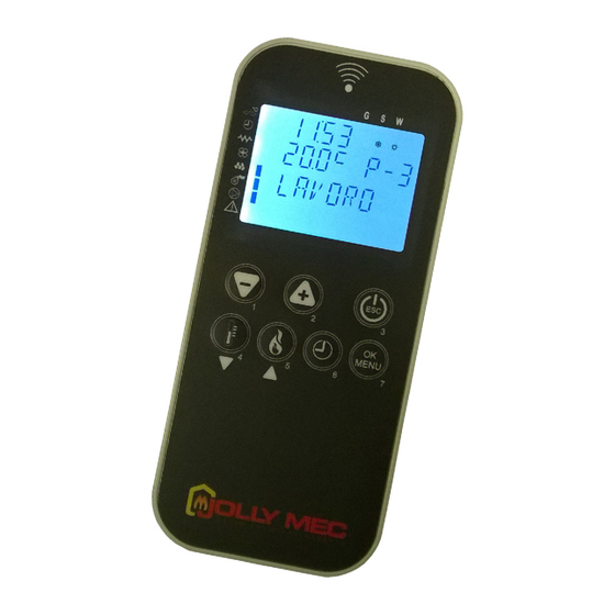
Week chronothermostat program Week-End chronothermostat program The image below depicts an example of a radio control screen which indicates that the chronothermostat function is running in the Week- End program and the auger gear motor and electrical resistance are running. -
Page 7: Emergency Console
02.4 EMERGENCY CONSOLE In the event radio control fault compromises good operations, the emergency console installed on the appliance can be used to run main functions such as ignition, shutdown and work output settings. On, off or alarm reset key. -
Page 8: Battery Installation And Replacement
BATTERY INSTALLATION AND REPLACEMENT The radio control is powered by two AAA alkaline batteries. In the event of radio control malfunctions, always check whether the batteries are charged. Otherwise, replace them with new ones of the same type. To replace the batteries, remove the cover on the back of the radio control, insert the batteries in the specific compartment as illustrated below (and as indicated inside the compartment). -
Page 9: Radio Channel Settings
02.6 RADIO CHANNEL SETTINGS To set the communication channel between the remote control and appliance control unit, at time necessary after replacing the batteries, turn off appliance power by turning the main switch to 0. Next, simultaneously press remote control keys 1 and 2 to display the SELECT UNIT X message. Use Keys 1 and 2 to set the required channel (X = from 0 to 7). -
Page 10: Display Backlight
02.8 DISPLAY BACKLIGHT The display backlight can be turned on by pressing Keys 1 and 7 in the initial screen simultaneously. The screen illustrated below will be displayed. Press Keys 1 or 2 to adjust backlight off delay time in seconds. After setting the required value, press Key 3 to confirm and exit settings. -
Page 11: Chap.03 Operating Mode
CHAP.03 OPERATING MODE 03.1 APPLIANCE OPERATIONS When the appliance is OFF, press and hold down Key 3 on the remote control for several seconds to turn it on. Next, the message ON will appear on the display indicating that the switch-on procedure has started made up of various phases defined in technical parameter settings set by a specialised Technical Service Center. -
Page 12: Main Status Message Meanings
03.3 MAIN STATUS MESSAGE MEANINGS During normal operations, the radio control screen displays the time, room temperature, output level and a message that indicates device status when the message is displayed. An illustration of the main display screen appears below. -
Page 13: Main Settings
03.4 MAIN SETTINGS The dedicated buttons on the remote control (Buttons 5 and 4) provide directly access from the main window to the work output and environment temperature value settings. Output settings To change the operating output, press Key 5 on the main page to immediately open the screen where you can use Keys 1 and 2 to select from the five settable output settings. -
Page 14: Chap.04 User Menu
CHAP.04 USER MENU 04.1 FUNCTIONS The display is divided into menus and sub-menus that can be scrolled using the radio control keys. In short, main menus and their functions are: MENU Description 1 - SET CLOCK Lets you set the current date and time, required for correct chronothermostat operations 2 - SET CHRONO Lets you turn the chronothermostat and its programs on or off. -
Page 15: Structure
04.2 STRUCTURE To open the various menus, press Key 7 when the main page is displayed on the remote control. To scroll the various menu pages, use Keys 4 and 5. MENU 1 - SET CLOCK Menu 01 DAY To select the current day of the week, use Keys 1 and 2 and press Key 7 to set the displayed value and move to the next page. - Page 16 (or shutdown). The countdown is not continuous but is refreshed when any radio control key is pressed. The appliance can be switched on (or shutdown) at any time even in this situation by using the normal procedure.
- Page 17 M2-2-001 ENABLE CHRONO Use Keys 1 and 2 to select to enable or disable the chronothermostat function and press Key 7 to confirm the selection and move to the next page. This function can be directly opened by pressing Key 6 on the main page.
- Page 18 M2-4-001 CRONO WEEK Use Keys 1 and 2 to select to enable or disable the CHRONO WEEK function and press Key 7 to confirm the selection and move to the next page. M2-4-002 START PROG- 1 Use Keys 1 and 2 to set the start time for the first operating time range permitted by the function and press Key 7 to confirm the selection and move to the next page.
- Page 19 M02-05-001 CHRONO WEEK-END Use Keys 1 and 2 to select to enable or disable the CHRONO WEEK-END function and press Key 7 to confirm the selection and move to the next page. M02-05-002 START 1 WEEK-END Use Keys 1 and 2 to set the start time for the first operating time range permitted by the function and press Key 7 to confirm the selection and move to the next page.
- Page 20 MENU 3 - SET LANGUAGE Menu 03 LANGUAGE Use Keys 1 and 2 to select the required language from the four available European languages (ITALIAN, ENGLISH, GERMAN and FRENCH) and press Key 7 to confirm. When finished, the message DONE will be displayed to confirm correct data entry.
- Page 21 MENU 6 - SET DISPLAY Menu 06 SET BUZZER Use keys 1 and 2 to mute the buzzer each time the remote control buttons are pressed, then press key 7 to confirm and move to the next page. The acoustic warning signal on the buzzer remains enabled for alarm signals.
- Page 22 MENU 8 - STATE STOVE M8-001 This page displays the fumes temperature, the fume fan speed, the work output, the load pellet time and the phase in progress M8-002 Display of the left ducting operating room temperature (for models with these settings) M8-003 Display of the right ducting operating room temperature (for models with these settings)
- Page 23 MENU 10 - SET ADJUST- Menu 10 ADJUST PELLET Use Keys 1 and 2 to adjust the quantity of pellets between -09 and -09 corresponding to ±3% each unit and press Key 7 to confirm and move to the next page. Menu 10 ADJUST CHIMNEY Use Keys 1 and 2 to adjust fume exhaust speed between -09 and -09 corresponding to ±3% each unit and press...
- Page 24 Menu 11 - FLOW EXCLUDED The number of exclusions of Coaxial Control system are displayed in this page (if available) Menu 11 - ALARMS MEMORY These pages display the alarms that have been triggered. Each alarm page displays the alarm code and text. Press button 5 to move from one alarm page to the MB-6 other four.
-
Page 25: Chap.05 Fault Diagnosis And Troubleshooting
CHAP.05 FAULT DIAGNOSIS AND TROUBLESHOOTING 05.1 ALARM MESSAGES Following is an overview on appliance alarms linked to the probable causes and some potential solutions. If an alarm occurs with a certain frequency, contact the specialised Technical Service Center. Alarm alert screens appear as illustrated below: Alarm code Alarm test Alarm cause... - Page 26 Alarm code Alarm test Alarm cause Main solution • The temperature falls below the OPERATING • Check that the level of PELLETS inside the AL06 THRESHOLD setting whilst the stove is running. hopper is sufficient PELLET • Check the PELLET load times are set correctly •...
- Page 27 Alarm code Alarm test Alarm cause Main solution • The motherboard temperature is over 60°C, non- • Check the pellet load values, they may be AL15 SAFETY modifiable value. excessive and cause overheating inside BOARD the stove cladding. • Check the heat exchange fan is working properly, otherwise it can cause overheating inside the stove cladding.
-
Page 28: Technical Specifications
05.2 TECHNICAL SPECIFICATIONS The device is constructed according to the following regulations: Industrial, scientific and medical radio frequency devices (ISM). Radio interference characteristics. Limits • CEI EN 55011 and measurement methods Electromagnetic compatibility (Part 3 Section – 2, Part 4 Sections -2, -4, -5, -6, -8, -9, -11, -29) •... - Page 29 NOTES...
- Page 32 Via S.Giuseppe 2 - 24060 Telgate (Bg) Italy Tel. +39 035.83.59.211 Fax +39 035.83.59.203 www.jolly-mec.it - info@jolly-mec.it...
Need help?
Do you have a question about the Radio Control and is the answer not in the manual?
Questions and answers