
Related Manuals for Velleman K7102


Summary of Contents for Velleman K7102
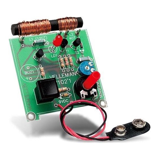
- Page 1 Total solder points: 47 Difficulty level: beginner 1 advanced METAL DETECTOR K7102 ILLUSTRATED ASSEMBLY MANUAL H7102IP-1...
-
Page 2: Specifications
Features & Specifications To come up against an electric cable while drilling a hole in a wall can have catastrophic consequences. Likewise, drilling into gas, water pipes or central heating pipes can be extremely hazardous. With a handy metal detector it can now be determined beforehand whether there are metal objects to be found in a wall, ceiling or floor. - Page 3 Assembly hints 1. Assembly (Skipping this can lead to troubles ! ) Ok, so we have your attention. These hints will help you to make this project successful. Read them carefully. 1.1 Make sure you have the right tools: • A good quality soldering iron (25-40W) with a small tip.
- Page 4 Assembly hints 1.3 Soldering Hints : 1- Mount the component against the PCB surface and carefully solder the leads 2- Make sure the solder joints are cone-shaped and shiny 3- Trim excess leads as close as possible to the solder joint REMOVE THEM FROM THE TAPE ONE AT A TIME ! DO NOT BLINDLY FOLLOW THE ORDER OF THE COMPONENTS ONTO THE TAPE.
- Page 5 Construction 2. Diode. Watch the polarity ! 1. Coils D1 : 1N4148 The coil consists of two windings around the ferrite core supplied. D... CATHODE In order to facilitate winding, thin double sided sticky tape can be stuck to the ferrite core, each winding can be held down using ordinary sello- tape.
- Page 6 Construction & connection 4. Resistors 6. Transistors. 8. Trim potentiometers R... T1 : BC547B RV1 : 2K5 T2 : BC547B RV2 : 100 T3 : BC547B R1 : 330 (3 - 3 - 1 - B) R2 : 470 (4 - 7 - 1 - B) 7.
- Page 7 Assembly 10. Assembly Connect the battery terminal to the point marked “+” (red) and “-” (black), see figure 2.0. Black Fig. 2.0 Connect the windings to their respective points marked with a, b, (L1) and c, d (L2), see figure 3.0. Fig.
- Page 8 Test 11. Test & final adjustments 1. Connect a 9V battery to the battery holder. 2. Go to a place where NO metal object is known to be in the vicinity. 3. Turn preset RV1 fully clockwise . 4. Turn RV2 fully anti-clockwise. 5.
- Page 9 Drill pattern 12. Drill pattern for optional G047 enclosure...
- Page 10 13. PCB layout.
- Page 11 Diagram 14. Diagram 1n2*...
- Page 12 Modifications and typographical errors reserved VELLEMAN NV © Velleman nv. Legen Heirweg 33, 9890 Gavere H7102IP - 2004 - ED1 (rev.1.0) Belgium - Europe 5 4 1 0 3 2 9 2 8 9 6 8 3...
Need help?
Do you have a question about the K7102 and is the answer not in the manual?
Questions and answers