Table of Contents
Advertisement
Advertisement
Table of Contents

Related Manuals for Lidén Weighing LI-101

Summary of Contents for Lidén Weighing LI-101
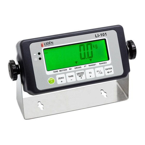
- Page 1 LI-101 User Manual...
-
Page 2: Table Of Contents
Table of Contents Safety Precaution ........................2 Chapter 1 Keyboad Instruction ....................3 Chapter 2 Specifications ......................4 Chapter 3 Front and Rear Panels ....................5 3-1 Front Panel ........................5 3-2 Rear Panel ........................6 Chapter 4 Installation ........................7 4-1 Load Cell........................ -
Page 3: Safety Precaution
Before using the product Thank you for purchasing LI-101 indicator. In order to operate smoothly, to last the durability, and to reduce the chance of breakdown for this product, please read the following User Manual carfully. Safety Precaution Turn off power before installing or disassembling. -
Page 4: Chapter 1 Keyboad Instruction
Chapter 1 Keyboad Instruction Function Operation Description Press and hold ENTER Refer to <Chapter 5> External General Function Setting Function Parameter Setting for details and then press Setting for decimal point, capacity, Weighing Parameter Adjust calibration division, zero tracking, and unstable detecting, etc. -
Page 5: Chapter 2 Specifications
Chapter 2 Specifications Analog Specification Load Cell Current: DC 5V −5% 60mA (Up to Four 350Ω Load Cells) Max. Load Cell Input Voltage: 16 mV Input Sensitivity: 0.15µV/D or more Conversion Rate: Approximately 120 times/sec. (max.) ... -
Page 6: Chapter 3 Front And Rear Panels
Chapter 3 Front and Rear Panels 3-1 Front Panel Indication: : Battery charged status (only available to charged model) : Battery charging status (only available to charged model) TARE : Tare status MOTION : Unstable weighing indication : Accumulation status indication GROSS : Gross weight : Pre-tare... -
Page 7: Rear Panel
3-2 Rear Panel 1. Battery Case 2. RS232/485 Input/Output 3. DC 9V Power Input 4. Calibration Switch 5. Load Cell Connect Socket Chapter 4 Installation 4-1 Load Cell Load cell cable Load cell EXC+ SEN+ SIG+ SIG- EXC- SEN-... -
Page 8: Load Cell
Shield 4-wired (5-wired) Load Cell 6-wired (7-wired) Load Cell Pin5 connects with EXC+ Pin 4, 5 short to connect with EXC+ Pin4 connects with SEN+ Pin 2, 3 short to connect with EXC- Pin3 connects with EXC- Pin 1 connects with SIG+ Pin 9 connects with SIG- Pin2 connects with SEN- Pin1 connects with SIG+... -
Page 9: Dimension
4-2 Dimension 225.0 ------6 0------- <1 : : , : : ; ; . . . J B IT1- , ; , "-=--- 49 . 5---- 193.0... -
Page 10: Battery Assemble
4-3 Battery Assemble Stuff the surplus wires into the battery case. 將多餘的電線塞入電池孔中... -
Page 11: Chapter 5 External Function Parameter Setting
Chapter 5 External Function Parameter Setting ENTER Under general weight display status, press , and the screen will display: ENTER Press TARE ZERO Press ENTER Press to escape. Back to general weight display status. External function setting RS232/RS485 interface function... -
Page 12: External Function Setting
5-1 External Function Setting ENTER Press *Parameter Code Key Disable Input the *parameter DSP Update (Display Update) code intended F1 Key Function Setting F2 Key Function Setting Press ENTER ENTER+F2 Function Setting Backlight Function Setting ... - Page 13 External Function Parameter Setting Default Parameter Setting Value Function Code Setting Parameter Description 0000 is corresponding to:(from left to right) 0000 0000 FNC-00 Key disable GROSS ZERO TARE 1111 1 OFF No Limit 20 times/sec. 10 times/sec. FNC-01 DSP Update 5 times/sec.
-
Page 14: Rs232 Setting
5-2 RS232 Setting *Parameter Code Information Pattern Press ENTER Transmission Method Transmission Rate Input the *Parameter Parity, Bit Length, Stop Bit code intended Unstable or Over Load Auto Transmission Condition Command Address Press ENTER ... - Page 15 OP-01 RS232 RS485 Interface Function Parameter Setting Value Default Function Code Parameter Description Setting Display Correspondingly Gross Weight Information Net Weight Pattern Tare RS1-00 (Please refer Weight Accumulation Value to page 16) Times Accumulation Value Output with Date & Time Continuous Transmission Auto Transmission Transmission...
- Page 16 No Limit 1 times/sec. 2 times/sec Transmission RS1-08 Times 5 times/sec 10 times/sec 20 times/sec Date Setting RS1-09 Time Setting RS1-10...
- Page 17 Transmission Format RS1-00 0 ~ 3 g CR LF Header 1 Header 2 Weight Data (8 digits) Unit Terminators Header 1 ST: Stable Weight / US: Unstable Weight / OL: Weight Overload Header 2 GS: Gross Weight / NT: Net Weight / TR: Tare Weight Data (8 digits) The first digit of weight data represents “+/-“indication for weight value.
- Page 18 Command Mode Command Function Command Function READ/RW Weight Reading Tare Clearing ZERO/MZ Weight Re-zeroing Weight Accumulation TARE/MT Gross Weight Deducting Times Accumulation NTGS Gross / Net Switch Date Gross Weight Indicating Time Weight and Times Net Weight Indicating Accumulation Weight and Times Accumulation Clearing ...
-
Page 19: Chapter 6 Internal Setting Mode
Chapter 6 Internal Setting Mode Adjust calibration switch to “ON”, and the screen displays: After 2 seconds ENTER Press TARE ZERO Press ENTER Press TARE ZE RO Press ENTER Adjust calibration switch back to “OFF”. Specification Setting Internal Weight Calibration ... -
Page 20: Specification Setting
6-1 Specification Setting *Parameter Code ENTER Press Decimal Point Maximum Weighing Capacity Division 1 Input the *Parameter Division 2 Code intended Zero Tracking Setting Unstable Detecting Setting ENTER Press The screen displays the parameters set previously. Input the parameters intended and then press ENTER Continue other functions setting... - Page 21 Specification Parameter Description Setting Value Default Parameter Function Code Description Setting Parameter Decimal Refer to the description on next CSP-00 Point page. Maximum 999999 Weighing CSP-01 Max. value for weight display 999999 Capacity 000000 Division 1 Min. value for weight display CSP-02 Division 2 Min.
- Page 22 Parameter Display Description CSP-00 Decimal Point Display Decimal Point Digit None 1 Digit 2 Digits 3 Digits 4 Digits CSP-04 Zero Tracking Setting Display Division/Time 0.25 D / 1 sec 0.5 D / 1 sec 0.75 D / 1 sec 1D / 1 sec 1.25 D / 2 sec 1.5 D / 2 sec...
-
Page 23: Internal Weight Calibration
6-2 Internal Weight Calibration Turn on and warm up the machine for 15 to 30 minutes before calibration. Adjust calibration switch to “ON”, and the screen will display Press to select TARE ZERO Procedure ENTER ENTER Zero Zero calibration completed Calibration ENTER Place the... - Page 24 Password Setting Adjust calibration switch to “ON” After 2 seconds ZERO Input new password “0000” means no password. ENTER Confirm new password (re-input again) ENTER After complete password setting, when entering calibration mode or function setting mode, the screen displays for 1 second, and then It’s necessary to input the correct password to continue each setting.
-
Page 25: Internal Function Setting
6-3 Internal Function Setting ENTER Press *Parameter Code Tare or Zero Function under Unstable Status Input the *Parameter Last Zero-recal function code intended Re-zero Range Filter Strength ENTER Press Animal Scale Sampling Rate Animal Scale Mode The screen displays ... - Page 26 Internal Function Parameter Description Parameter Setting Value Default Function Code Parameter Description Setting Tare or Zero CFN-00 Function under Unstable Status Last Zero-recal CFN-01 function 0%: Full range re-zero 1% ~ 30%: CFN-02 Re-zero Range 0% ~ 30% Capacity • − setting value% CFN-03 Filter Strength 0 ~ 5...
-
Page 27: Error Messages
6-4 Error Messages Load Cell or A/D circuit extraordinary Real weighing value ≦ zero value Internal resolution < 0.15μV/D range Incorrect password Turning on zero < zero range Turning on zero > zero range... -
Page 28: Chapter 7 Special Function
Chapter 7 Special Function 7-1 Animal Scale Setting CFN-05 = 1 (Animal Scale Mode1: No weight display under unstable status) When there is nothing on the platter, the screen will display: When the object is on the platter, after weight has been measured, the screen will display: If the display weight value keeps being lower than zero plus 10d or press Enter key to start weighing, then the screen will display:... -
Page 29: Dual Range Resolution Switch Function
7-2 Dual Range Resolution Switch Function If the setting of CSP-02 is not the same as CSP-03, the dual range resolution will be activated. CFN-08 = 0 Multi - interval If CFN-09 = 5000 Division 2 最小刻度2 5000 最小刻度1 Division 1 ... -
Page 30: Pre-Tare Function
Pre-tare Function FNC-02 or FNC-03 setting is at parameter 6. (Pre-tare Function) Under weight display status, press key (according to FNC setting), the screen will display: Input the pre-tare value intended Press ENTER Back to weight display status (PT indication lights up) Pre-tare Cancellation TARE When the gross weight is displayed as “0”, press... -
Page 31: Peak Hold Function
7-5 Peak Hold Function Description Description <ZERO/+> Increase the flash value by one <GROSS/NET> Move the cursor leftward <TARE/-> Decrease the flash value by one <F2> Move the cursor rightward <ENTER> Confirm / Enter key <ESC> Abort setting or exit Detailed procedures 1. -
Page 32: Chapter 8 Interface
Chapter 8 Interface 8-1 OP-01 RS232/RS485 Serial Output with RTC (Real Time Clock) 1 2 3 1 2 3 To short 1 and 2 pins is RS485 output. To short 2 and 3 pins is RS232 output. Pin Allocation of Rear Panel Function ... - Page 33 Connection Description (RS485) Terminal Resistant 終極電阻 Host 電腦主機 EX0419 # 1 RS - 06 = 01 EX0419 # 2 RS - 06 = 02 EX0419 # 10 RS - 06 = 10 Notice ∅ If the terminal resistant is built-in the host interface, it ’s not necessary to connect with another one outside.
-
Page 34: Chapter 9 Maintenance
Chapter 9 Maintenance 9-1 Default Recovery for All Parameters (1) Adjust the calibration switch to “ON”, when re-zeroing after turning on, press and hold simultaneously. ENTER (2) The screen will display ENTER (3) If decided, press and hold until displaying , and then adjust the calibration switch to “OFF”. -
Page 35: Program Version Number
9-3-1 Program Version Number 7-segment display reveals program version number 9-3-2 7-segment Display Testing 7-segment display reveals ~ and “ ”. 9-3-3 Keypad & Calibration Switch Testing Adjust calibration switch to “ON”, and press any key, the correspondin g bit will be changed from 9-3-4 AD Conversion Value 7-segment display reveals the internal value of the present wei ght. -
Page 36: Appendix 7-Segment Display Characters
Appendix 7-SEGMENT DISPLAY CHARACTERS 7-Segment 7-Segment 7-Segment Digit Alphabet Alphabet Letter Letter Letter ℃...
Need help?
Do you have a question about the LI-101 and is the answer not in the manual?
Questions and answers