
Summary of Contents for Miyachi Amada ISQ20 Series
- Page 1 Original Instructions: German Translation of Original Instructions Inverter Power Source ISQ20 Series OPERATING INSTRUCTIONS 76609605EN-ISQ20-V1.2...
- Page 2 New declaration of conformity (CE) Copyright 2016: AMADA MIYACHI EUROPE GmbH Lindberghstr. 1, 82178 Puchheim, Germany Right to make amendments reserved. Deviations may occur. All rights reserved. The products named in this manual are only used for identification purposes and may be trademarks or registered trademarks of the respective companies.
-
Page 3: Table Of Contents
ISQ20 Content Content 1 General Information ..................... 5 Safety Notes ........................5 Installation Notes ....................... 6 Declaration of Conformity ....................7 2 Technical Description ..................8 Device Types ........................9 2.1.1 Technical Data ISQ20-3-DC ...................... - Page 4 ISQ20 Content 5 Commissioning ....................36 Preconditions for Commissioning ................. 36 Electrical Connections ....................36 5.2.1 Mains Supply ........................... 37 5.2.2 Connecting Secondary Cables ......................38 5.2.3 Connecting Current Measurement ....................39 ...
-
Page 5: General Information
ISQ20 General Information General Information Safety Notes Information about safety regulations, symbols, copyrights, protection rights, usage location conditions and notes on resistance welding can be found in the back section of these operating instructions. Please read this information carefully before using these operating instructions. These operating instructions should help you familiarize yourself with the system and take advantage of its application possibilities when used as directed. -
Page 6: Installation Notes
ISQ20 General Information Installation Notes Please observe the following additionally to the points in chap. 5.1: Ventilation: To ensure adequate ventilation of the weld control and motor control units, the distance on the side must be at least 40 mm and behind at least 100 mm. 19“... -
Page 7: Declaration Of Conformity
ISQ20 General Information Declaration of Conformity 76609605EN-ISQ20-V1.2.docx 7/63... -
Page 8: Technical Description
ISQ20 Technical Description Technical Description The inverter power supply ISQ20 (hereinafter also referred to as inverter or weld control) can be used as a stand-alone unit with the operating terminal MFT1 or as part of the AWS3 (Active Welding System 3) with the operating terminals OP-AWS3 or TP-AWS3. -
Page 9: Device Types
ISQ20 Technical Description Device Types The ISQ20 is available in the following DC- and AC types: DC device with internal transformer: 3 kA ISQ20-3-DC 6 kA ISQ20-6-DC DC device with external transformer: 10 kA consisting of basic device ISQ20-10-DC ISQ20-EXT-AC/DC-250 and transformer IT-60X * DC device with external transformer and external line filter: 20 kA... -
Page 10: Technical Data Isq20-3-Dc
ISQ20 Technical Description 2.1.1 Technical Data ISQ20-3-DC 3x 400 VAC, ±10%, PE Supply voltage 50...60 Hz Mains frequency 4 x 2.5 mm² Connecting cable 11 kVA Connected load 3 x 16 A, slow Fuse recommended 2 kA at 11 % d.r. Rated output current measured for Tu = 20 °C 3 kA... -
Page 11: Technical Data Isq20-6-Dc
ISQ20 Technical Description 2.1.2 Technical Data ISQ20-6-DC 3x 400 VAC, ±10%, PE Supply voltage 50...60 Hz Mains frequency 4 x 2.5 mm² Connecting cable 11 kVA Connected load 3 x 16 A, slow Fuse recommended 3 kA at 20 % d.r. Rated output current measured for Tu = 20 °C 6 kA... -
Page 12: Technical Data Isq20-10-Dc
ISQ20 Technical Description 2.1.3 Technical Data ISQ20-10-DC with IT-60X transformer: 3 x 400 VAC, ±10 %, PE Supply voltage 50...60 Hz Mains frequency 4 x 6 mm² Connecting cable 22 kVA Connected load 3 x 32 A, slow Fuse recommended dep. -
Page 13: Technical Data Isq20-20-Dc
ISQ20 Technical Description 2.1.4 Technical Data ISQ20-20-DC with IT-113X transformer: 3 x 400 VAC, ±10 %, PE Supply voltage 50...60 Hz Mains frequency 4 x 35 mm² Connecting cable 85 kVA Connected load 3 x 100 A, slow Fuse recommended dep. -
Page 14: Technical Data Isq20-8-Ac
ISQ20 Technical Description 2.1.5 Technical Data ISQ20-8-AC with TRM3/14 transformer: 3 x 400 VAC, ±10 %, PE Supply voltage 50...60 Hz Mains frequency 4 x 6 mm² Connecting cable dependent on main stage Connected load dependent on main stage Fuse recommended dep. -
Page 15: Operation
ISQ20 Technical Description Operation The operation of the ISQ20 is made with one of the following operating terminals: AWS3 operating terminal with toggle wheel OP-AWS3: AWS3 operating terminal with touch panel TP-AWS3: Operating terminal with buttons MFT1: Find more information regarding the operating terminals in the respective operating instruction. -
Page 16: Maximum Duty Ratio
ISQ20 Technical Description Maximum Duty Ratio Duty ratio (d.r.) relative to the set welding current: ISQ20-3 ED… I in kA ISQ20-6 ED… I in kA Fig. 2: Maximum duty ratio For ISQ20 with external transformer (ISQ20-8, ISQ20-10 and ISQ20-20) the duty ratio is dependent on the used transformer. -
Page 17: Design And Mode Of Action
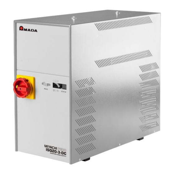
ISQ20 Design and Mode of Action Design and Mode of Action Front Panel ISQ20 Main switch Status display and error messages RS232 Fig. 3 Front panel On the front panel you find: the main switch the RS232 interface ... -
Page 18: Rear Panel Isq20-3 / Isq20-6
ISQ20 Design and Mode of Action Rear Panel ISQ20-3 / ISQ20-6 Abb. 5: Rear panel ISQ20-3 / ISQ20-6 76609605EN-ISQ20-V1.2.docx 18/63... -
Page 19: Rear Panel Isq20-8 / Isq20-10
ISQ20 Design and Mode of Action Rear Panel ISQ20-8 / ISQ20-10 Abb. 6: Rear panel ISQ20-8 / ISQ20-10 76609605EN-ISQ20-V1.2.docx 19/63... -
Page 20: Rear Panel Isq20-20
ISQ20 Design and Mode of Action Rear Panel ISQ20-20 Abb. 7: Rear panel ISQ20-20 76609605EN-ISQ20-V1.2.docx 20/63... -
Page 21: Connections
ISQ20 Connections Connections Overview Name Description Mode Power connection Binary inputs BIN IN DSUB 37 Binary outputs BIN OUT DSUB 37 socket Initiators DIST DSUB 25 socket Valves RESOLVER DSUB 15 socket Start START Binder 6+PE socket Proportional valve head 1 Binder 7-pol. -
Page 22: Data Output Format, Aws3 Mode
ISQ20 Connections 4.2.2 Data Output Format, AWS3 Mode Default with OP-AWS3/TP-AWS3 Character string Description Digits Program number Space Axis 1 or axis 2 Space Peak current pulse 1 [kA] Is1_kA Space RMS current pulse 1 [kA] Ie1_kA Space Peak voltage pulse 1 [V] Us1_V Space RMS voltage pulse 1 [V]... -
Page 23: Data Output Format, Classic Mode
ISQ20 Connections 4.2.3 Data Output Format, Classic Mode Default with MFT1. Classic mode in combination with AWS3 is only recommended, if compatibility with older previous units has to be enabled. Character string Description Digits Program number Space Peak current pulse 1 [kA] Is1_kA Space Peak voltage pulse 1 [V]... -
Page 24: Plug Assignments
ISQ20 Connections Plug Assignments 4.3.1 Binary Inputs, potential free DSUB 37 - pin Function Note without current 2.5 mA at 24 V Setup, run without current X1.1 Reset counter 2.5 mA at 24 V All counters (w/o action counter) X1.2 Reset Out Of 2.5 mA at 24 V If set, error „Out of Limits“... - Page 25 ISQ20 Connections Function Note Ini 2 head 2 2.5 mA at 24 V Necessary with two stroke cylinders or two X1.19 back/top pincers. Display shows error, if welding head is not back. See also connector X3.4. Ini 3 stroke 1 2.5 mA at 24 V Necessary with one stroke cylinder.
- Page 26 ISQ20 Connections Function Note External part 2.5 mA at 24 V Limits for displacement ok, displacement X1.27 detection ok head measuring device has to be connected. Special case for pneumatic head and activated (internal) displacement measuring: Activation option reference run head Thermo switch 2.5 mA at 24 V Error 73:...
-
Page 27: X2: Binary Outputs, Potential Free
ISQ20 Connections 4.3.2 Binary Outputs, potential free DSUB 37 - socket Function Note Ready 100 mA at 24 V The ready LED (green) shows whether a X2.1 welding can be started. Unit has to be “ready” before start is set (i.e. Quick Stop is not released and unit is in a welding menu). - Page 28 ISQ20 Connections Function Note Valve 1 X2.15 Valve 2 X2.16 +24 V DC also See also connector X4.1. Valve 3 switched; X2.17 chap. function depends on control mode 100 mA at 24 V Valve 4 X2.18 Valve 5 X2.19 Out of limits tw, I, 100 mA at 24 V X2.20 U, P Kopf 1...
- Page 29 ISQ20 Connections Function Note Out of limits head 2 100 mA at 24 V The actual welding value (depending on the X2.28 control mode current /voltage / power) is checked for deviations from rated value. If deviation is greater than specified by maximum and minimum value (limits and curves), this output is set.
-
Page 30: X3: Initiators
ISQ20 Connections 4.3.3 Initiators DSUB 25 - socket Function Note INI1: head 1 24 V at head Necessary with one stroke cylinder or pincers. X3.1 back/top back Display shows error if welding head is not back INI1_+24V Supply voltage X3.2 +24 V INI1_GND 0 V ext. - Page 31 ISQ20 Connections Function Note DS1_+24V Supply voltage X3.20 +24 V DS1_GND 0 V ext. X3.21 (ref. to 24 V) Pressure switch A second connected pressure switch X3.22 2. Signal signalizes that welding pressure in head 2 has been achieved. The input is queried before the current time starts.
-
Page 32: X4: Valves
ISQ20 Connections 4.3.4 Valves DSUB 15 - socket Function Note Valve triggering 1 +24 V Function depends on control mode, see X4.1 chap. 5.3.1 VV1_GND 0 V ext. (ref. to 24 V) X4.2 VV1_PE Protective earth X4.3 Valve triggering 2, +24 V Function depends on control mode, see X4.4 chap. -
Page 33: X6: Proportional Valve Head 1
ISQ20 Connections 4.3.6 Proportional Valve Head 1 Binder 7 - socket Function Note PVV_OUT Input actual value 1 From pressure sensor on the welding head X6.1 (“actual value”) (0..10 V) or from proportional valve “actual value” (no pressure sensor). If this input is used, the toggle switch S1 must point in the direction of X6. -
Page 34: X9: Pressure Sensor Head 2
ISQ20 Connections 4.3.9 Pressure Sensor Head 2 Binder 4 - socket Function Note PS_+24V +24 V supply voltage X9.1 PS_GND 0 V ext. X9.2 (ref. to 24 V) PS_OUT Input actual value 2 From pressure sensor on the welding head X9.3 (“actual value”) (0..10 V) or from proportional valve “actual value”... -
Page 35: X30: Welding Transformer
ISQ20 Connections 4.3.13 X30: Welding Transformer Terminals Function Positive primary voltage X30.1 Negative primary voltage X30.2 X30.3 4.3.14 X31: Temperature Sensor Transformer Terminals Function Thermo safety plug 1 X31.3 Thermo safety plug 2 X31.4 4.3.15 X32: Current Measuring Coil Terminals Function Current measuring contact 1 X32.1... -
Page 36: Commissioning
ISQ20 Commissioning Commissioning Preconditions for Commissioning Stand-alone devices have to be placed firmly and stable on a table or a rack. Built-in devices have to be mounted firmly and stable in a control cabinet or on a table rack. Caution ... -
Page 37: Mains Supply
ISQ20 Commissioning 5.2.1 Mains Supply Note mains voltage! Warning First compare the existing connection voltage to the voltage stated on the type label of the equipment. An intermediate power circuit of approx. 560V is created from the 3 phase 230/400 VAC / 50/60 Hz mains power supply in the inverter. -
Page 38: Connecting Secondary Cables
ISQ20 Commissioning 5.2.2 Connecting Secondary Cables Use secondary cables with 95 mm² cross- section and a length of at least 500 mm. Use M8 x 16 mm fixing screws. Connect one secondary cable with the (+) pole of the ISQ20 (resp. the transformer) and the active electrode (at the corresponding connection behind the current band on the welding... -
Page 39: Connecting Current Measurement
ISQ20 Commissioning 5.2.3 Connecting Current Measurement A current measuring coil must be integrated in the secondary circuit for all inverters with external transformer (ISQ20-8, ISQ20-10, ISQ20-20). (Standard: Toroidal ring coil ø 70 mm, no. 770.60 152). The current measuring coil is part of the power control or oft he measuring unit (if used). Always make sure that only the supply cable of the secondary current is enclosed by the coil. -
Page 40: Mechanical Connections
ISQ20 Commissioning Mechanical Connections 5.3.1 Connection Possibilities Heads / Valves etc. The most common connection types for different welding tasks are listed in the following tables. Legend (alphabetical) of abbreviations in the following tables: Option, can be connected KV ZU Compacting unit closed Proportional valve Closing pressure... -
Page 41: Connection With One Head And Start 1
ISQ20 Commissioning 5.3.2 Connection with One Head and Start 1 76609605EN-ISQ20-V1.2.docx 41/63... -
Page 42: Connection With Two Heads And Start 1, 2 Or 3
ISQ20 Commissioning 5.3.3 Connection with Two Heads and Start 1, 2 or 3 76609605EN-ISQ20-V1.2.docx 42/63... -
Page 43: Insulation Test
ISQ20 Commissioning Insulation Test We use power supply filters in our units to meet European EMC regulations. These filters have a discharge resistance to earth in each phase which is illustrated below. The resistance value is 1 M in each case. This results in an effective resistance of 333 k for a cumulative insulation resistance measurement (L1-L2-L3 to earth). -
Page 44: Sequence
ISQ20 Sequence Sequence The chronological sequence of signals and functions is illustrated in the diagrams. The following diagrams are examples and cover a broad application range. Standard Diagram with One Head 10 ms or as long stepping as start 1 contact current program (option) -
Page 45: Diagram For One Head With Stroke Cylinder
ISQ20 Sequence Diagram for One Head with Stroke Cylinder 10 ms or as long stepping as start 1 contact current program (option) off-time 2 impulses pressure contact closes (option); head cushioned with adjustment cylinder proportioanal valve; welding pressure spring biased with adjustment cylinder valve 2 welding pressure with closing stroke... -
Page 46: Diagram For Pincers Resp. Locking Cylinder
ISQ20 Sequence Diagram for Pincers resp. Locking Cylinder 10 ms or as long as start 1 stepping contact current program (option) off-time 2 impulses pressure contact closes (option); head cushioned with adjustment cylinder proportioanal valve; welding pressure spring-biased with adjustment cylinder Valve 2 welding pressure with closing stroke valve 1 closing stroke;... -
Page 47: Error Messages
ISQ20 Error Messages Error Messages Each error is displayed twice: As digits in the 2-position Status display and additionally on the display of the operating terminal with number and plain text. Unit Errors (#10 – #59) No. Message Cause SQC3: EMERGENCY STOP active SQC3: Undervoltage intermediate UZK <... - Page 48 ISQ20 Error Messages No. Message Wrong answer from SQC3 No communication with SQC3 Error when deleting flash Error while writing on flash sector 1 Error while writing on flash sector 2 Error during transfer to terminal Current too high! (> maximum current) Current too low! (<...
-
Page 49: Sequence Errors (#60 - #95)
ISQ20 Error Messages Sequence Errors (#60 – #95) Message Cause Contact cylinder 1 not ahead (X3.7) Error pressure switch 1 Head not back (X3.1) Contact cylinder 1 not back (X3.13) Current greater than maximum current Start set when switching on Pressure deviation 1 too big Stroke cylinder 1 not in initial position Head 1 not down (X3.1) -
Page 50: Connection Variants (Examples)
ISQ20 Connection Variants (Examples) Connection Variants (Examples) In the following drawings the article numbers for cables always refer to cable with standard length (3 m). ISQ20 - pneumatic 1-Head w/o Distance Measurement 76609605EN-ISQ20-V1.2.docx 50/63... -
Page 51: Isq20 - Pneumatic 1-Head W/O Distance Measurement
ISQ20 Connection Variants (Examples) ISQ20 - pneumatic 1-Head w/o Distance Measurement 76609605EN-ISQ20-V1.2.docx 51/63... -
Page 52: Aws3 - Pneumatic 1-Head
ISQ20 Connection Variants (Examples) AWS3 - pneumatic 1-Head 76609605EN-ISQ20-V1.2.docx 52/63... -
Page 53: Aws3 - Pneumatic 2-Head
ISQ20 Connection Variants (Examples) AWS3 - pneumatic 2-Head 76609605EN-ISQ20-V1.2.docx 53/63... -
Page 54: Aws3 - Pneumatic With Profibus
ISQ20 Connection Variants (Examples) AWS3 – pneumatic with Profibus 76609605EN-ISQ20-V1.2.docx 54/63... -
Page 55: Aws3 - Pneumatic With Ethernet Ip
ISQ20 Connection Variants (Examples) AWS3 – pneumatic with Ethernet IP 76609605EN-ISQ20-V1.2.docx 55/63... -
Page 56: Aws3 - Motorized 1-Head
ISQ20 Connection Variants (Examples) AWS3 - motorized 1-Head 76609605EN-ISQ20-V1.2.docx 56/63... -
Page 57: Aws3 - Motorized 2-Head
ISQ20 Connection Variants (Examples) AWS3 - motorized 2-Head 76609605EN-ISQ20-V1.2.docx 57/63... -
Page 58: Aws3 - Motorized 1-Head With Profibus
ISQ20 Connection Variants (Examples) AWS3 - motorized 1-Head with Profibus 76609605EN-ISQ20-V1.2.docx 58/63... -
Page 59: Aws3 - Motorized 1-Head With Ethernet Ip
ISQ20 Connection Variants (Examples) 8.10 AWS3 - motorized 1-Head with Ethernet IP 76609605EN-ISQ20-V1.2.docx 59/63... -
Page 60: Aws3 - Motorized 1-Head With Router (Remote Service)
ISQ20 Connection Variants (Examples) 8.11 AWS3 – motorized 1-Head with Router (Remote Service) 76609605EN-ISQ20-V1.2.docx 60/63... -
Page 61: Connection Schemes
ISQ20 Connection Schemes Connection Schemes Binary Connections 1 76609605EN-ISQ20-V1.2.docx 61/63... -
Page 62: Binary Connections 2
ISQ20 Connection Schemes Binary Connections 2 76609605EN-ISQ20-V1.2.docx 62/63... -
Page 63: Index
ISQ20 Index Index 10.1 Illustration Index Fig. 1: Standard device ........................8 Fig. 2: Maximum duty ratio ......................16 Fig. 3 Front panel......................... 17 Abb. 4 Display ..........................17 Abb. 5: Rear panel ISQ20-3 / ISQ20-6 ..................18 ...
Need help?
Do you have a question about the Amada ISQ20 Series and is the answer not in the manual?
Questions and answers