Table of Contents
Advertisement
Quick Links
Advertisement
Table of Contents

Summary of Contents for Automatic Mirage M 801E
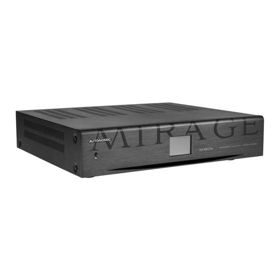
- Page 1 Mirage m·801e Multi-Zone Digital Amplifi er Manual...
-
Page 2: Important Safety Instructions
Important Safety Instructions Precautions Do not use this device near water water AC Fuse 10. Refer all servicing to qualified service or expose to excessive moisture. The AC fuse inside the device is not personnel. Unplug the device from user-serviceable. If you cannot turn on the wall outlet and refer servicing to Clean only with a dry cloth. -
Page 3: Declaration Of Conformity
A Note About Recycling b. Do not leave rubber or plastic items CE - European Conformity Information on this device for a long time as they This equipment bares the CE marking This product’s packaging materials are may leave marks on the case. of conformity that indicates a product recyclable and can be reused. -
Page 4: Table Of Contents
Table of Contents Important Safety Instructions Precautions Declaration of Conformity Supplied Accessories Features Front Panel Guide Rear Panel Guide Typical System Configuration Multiple Amplifier Stacks Controller Wiring Menu Navigation Ethernet / RS232 Protocol Specifications... -
Page 5: Features
Features Thank you for purchasing an M-801e Mirage Multi-Zone Amplifier. Please read this manual thoroughly before making connections and plugging in the device. Following the instructions in this manual will enable you to obtain optimum performance and listening enjoyment from your new Multi-Zone Amplifier. Please retain this manual for future reference. •... -
Page 6: Front Panel Guide
Front Panel Guide Front Panel Power Indicator Chassis Feet Solid Aluminium front Panel. The power indicator glows blue whenev- Set high enough to provide unrestricted er AC power is applied. air-flow through the chassis for convec- Infra-Red Receiver tion cooling. Receiver for front panel IR control (Used 2.4”... -
Page 7: Rear Panel Guide
Rear Panel Guide AC Inlet Ethernet Port – MAIN IN 11. Optical Digital Inputs IEC socket MAIN IN is 10/100 Base T primary Eth- Optical (TOSLINK) digital inputs. ernet port for connection to the Home Speaker Terminals 12. Controller Interface network. -
Page 8: Typical System Configuration
Typical System Confi guration Zone 1 KP-6 Zone 2 Study KP-iOS Zone 3 Lounge Tablet To Ethernet Router Mirage Media Server Satellite Receiver Tuner CD Player FIGURE 1... - Page 9 Typical System Configuration (Continued) Fig. 1 depicts a typical configuration where Speakers M-801e amplifier is providing audio Speakers in each zone are connected to the into six of the possible eight listening zones. amplifier by "Home Run" speaker cables. Only three of the zones are depicted. Source Equipment Each zone consists of a room with M-801e...
-
Page 10: Multiple Amplifier Stacks
Multiple Amplifi er Stacks To Ethernet Router Linking to the Next M-401e or M-801e Multi-Zone Amplifi er Mirage Media Server Satellite Receiver In large installations where multiple M-801e Tuner amplifi ers are required, Ethernet conveys amplifi er control, and link to other Media sources if connected to the Home network Router or Switch. -
Page 11: Controller Wiring
Controller Wiring The M-801e is packed with control options: • USB: Intended for initial installation Programming or firmware update. Not intended for permanent connection to a PC or other control system. • ETHERNET: Two 100BaseT connections to a home network or to daisy chain other amplifiers. •... -
Page 12: Menu Navigation
Menu Navigation Front Panel User Interface The M-801e amplifi er has a 2.4” Touch Panel LCD color display which is used for control and accessing status of all amplifi er functions. After 2 minutes of inactivity the LCD dims to 50% brightness. After a further 15 minutes it dims OFF. A touch of the screen will restore the LCD to full brightness, enabling touch control. ZONE SELECTION AQUARIUM FRI 9:33 AM... - Page 13 Menu Navigation (Continued) MAX VOLUME BALANCE NAME: AQUARIUM ZONE NAME: AQUARIUM EDIT ZONE LINKING A B C D E F ZONE: 100 G H I J K L M N O P Q R S T U V W X Y Z Levels Setup Page Zones Setup Page Zone Name Page...
- Page 14 Menu Navigation (Continued) INTERNET TIME / TIME ZONE SOURCE SETTINGS GAIN (Analog Input) A B C D E F FRI 9:33:06 PM UTC - 4:00 (Daylight Savings Time) G H I J K L M N O P Q R S T U V W X Y Z GET TIME...
-
Page 15: Ethernet / Rs232 Protocol
Ethernet Protocol The serial port provides data acquisition and control of the Mirage amplifiers by a home automation system, or PC. The interconnecting cable must be "Straight Through." For Ethernet, TCP port 17037 is used. Command Structure: <command> <zone> <data> <line feed> Command Command Description... - Page 16 Data Command Content Standby 00 – Standby OFF (01) 01 – Standby ON 04 – Toggle Mute 00 – Mute (02) 01 – Un-mute 02 – Toggle Mute Source Selection 00 – S5 04 – S8 (03) 01 – S6 05 –...
-
Page 17: Specifications
Notes Specifications • Commands are used as notifications. If an M·801e amplifier is switched ON, it will notify the other devices on the Control Bus by sending Rated Output Power (FTC) 50W per channel (100W per zone), 8Ω loads the Standby command (01). Any amplifiers All Channels with the same zone will take the notifica- Total Harmonic...
Need help?
Do you have a question about the Mirage M 801E and is the answer not in the manual?
Questions and answers