Advertisement
MICRON VIDEO INTERCOM
USER MANUAL
MODEL: IMTB
micron
Thank you for purchasing our products.
Carefully read this User's Guide(in particular, precautions for safety) before using a
product.
This product is subject to change without prior notice.
The company is not responsible for any safety accidents caused by abnormal operation
of the product.
Advertisement
Table of Contents

Subscribe to Our Youtube Channel
Summary of Contents for Micron IMTB
- Page 1 MICRON VIDEO INTERCOM USER MANUAL MODEL: IMTB micron Thank you for purchasing our products. Carefully read this User's Guide(in particular, precautions for safety) before using a product. This product is subject to change without prior notice. The company is not responsible for any safety accidents caused by abnormal operation...
-
Page 2: Table Of Contents
Index 1、Warning and Caution 2、The function and name of each part 3、Terminal wiring diagram 4、Features and main function 5、Package contents 6、System layout 7、Wiring diagram 8、Installation method 9、Cable specification 10、Functions in common use 11、System main menu 12、Specification Version: V1.0... -
Page 3: 1、Warning And Caution
1、Warning and caution Make sure to follow the instructions to prevent any danger or property losses. It indicates prohibition. Warning It indicates disassembly. Death or serious injury is expected. It indicates prohibition of contact. It indicates dos and don’ts. It indicates that the plug should be pulled out from the socket. - Page 4 It indicates prohibition. Caution It indicates disassembly. A injury or property losses are expected. It indicates prohibition of contact. It indicates dos and don’ts. It indicates that the plug should be pulled out from the socket. CAUTION T h e s o c k e t h o l e s a r e l a g e r t h a n u s u a l .
-
Page 5: 2、The Function And Name Of Each Part
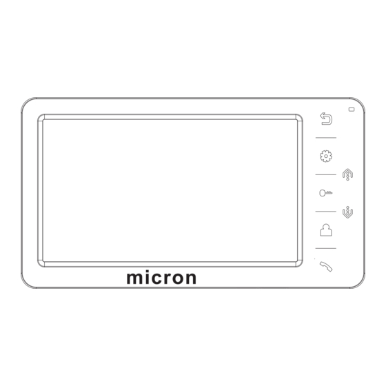
2、The function and name of each part 1). Return button: Return/hang up 2). Indicator light: Power indicator light 3). Menu button: Enter system menu/Confirm 4). Navigation button Up: Choose/Adjust 5). Unlock button: Unlock 6). Navigation button down: Choose/ Adjust 7). Monitor button: Monitor 8). -
Page 6: 3、Terminal Wiring Diagram
3、Terminal wiring diagram SLAVE MONITOR CCTV DOOR2 DOOR1 PORT 4 PORT 3 PORT 2 PORT 1 PORT 3 PORT 1 PORT 4 PORT 2 For External power supply 4、Features and main function MODEL LIST 1).Features 7" color screen Hands free design Comfortable touch button OSD menu with various setting 12 chord call melodies... -
Page 7: 5、Package Contents
2).Main functions Lock control Brightness, contrast, talk volume, color and display mode adjustable. Real-time monitoring of door station or CCTV camera “Do not disturb” function Broadcast and intercom call to other monitors Monitor listening to other indoor monitors Call transfer to other indoor monitors 5、Package contents Wall bracket Desiccant... -
Page 8: 7、Wiring Diagram
7、Wiring diagram Solution1 A D - 1 CCTV1 G N D CCVT1 G N D DATA CCTV2 V D - 1 CCVT2 G N D ROOM1 A D 1 A D 2 G N D G N D G N D G N D PWR1 PWR2... -
Page 9: 8、Installation Method
8、Installation method SINGLE MONITOR INSTALLATION 1. Refer to relevant wiring diagram for the system you have chosen and ensure you have the correct cable. 2. Determine the monitor installation position: -suggest to install at 1.5~1.6Meters; 3. Ensure no power supply connection before installation finished 4. -
Page 10: 9、Cable Specification
Cable Specification 9、Cable specification Our system has 2 solutions to unlock the door: Unlock signal from door station or unlock signal from monitor.(The cable shield wire needs to be grounded) Cable specification is: Distance between monitor and door station is less than 30 meters, shielded 4 x 0.5mm²... -
Page 11: 10、Functions In Common Use
10、Functions in common use 1). How to answer the call and transfer the call to other indoor monitors When call from door station or other indoor monitor, the indoor monitor(s) will chime, short press to answer the call. If no one answers, the monitor(s) shall be back to standby status after chime time end. - Page 12 3). How to make internal call At standby status, user can short press to entre intercom call interface, then short press to choose call target, press to confirm calling. For indoor monitors installed in multi- apartment system, user can input target room no.
- Page 13 7). How to set the address of indoor monitor. The default address is Room1. Optional Room1~Room4. The master monitor which connects to door station directly, should be set as Room1. If the system has 2 or more than 2 indoor monitors, can’t set a same address in 2 monitors, or the system can’t work normally &...
- Page 14 (A). VCOMDC: It's for adjusting the sharpness of the LCD. The factory has set a most suitable value before the products leaving the factory. Please do not change it casually, or the screen may not display normally. (B). UNLOCK TIME: It can be set from 1S to 10S. Note: most electric locks only need 1 second unlocking time, please do not change it if there’s no such needs for your lock, because too long time unlock power might cause damage to your lock.
-
Page 15: 11、System Main Menu
11、System setting In standby status ,press button to enter system setting menu. Setting items Options Notes LANGUAGE Default English(Russian optional) CHIME TIME Default 30seconds。(10~60 seconds adjustable) CHIME VOLUME Default 07, 01~10 adjustable. Door1 ring type 01 by default, 00-11 optionals RING TYPE Door2 ring type 02 by default , 00-11 optionals... -
Page 16: 12、Specification
12、Specification Content ltems AC100-240V 50/60Hz Power supply DC 15V 1A(External) 7W(Max). Power consumption 0.7W(Standby) Operation 0℃ to +40℃ temperature Operation humidity 7 inch LCD size Intercom mode Hands-free Connection 4 wires 210*116*25mm Dimension Weight 430g The parameters of product are subject to changes without prior notice. Page 14...
Need help?
Do you have a question about the IMTB and is the answer not in the manual?
Questions and answers