Advertisement
Quick Links
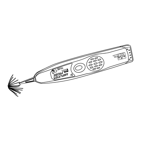
Amplifier Probe
Features
Specifications
Power requirements
The Amplifier Probe is designed to identify and trace wires or
•
One 9 Volt battery
cables within a group without damaging the insulation
Battery Life
Works with any Tone Generator (62-160) to identify wires
•
(Alkaline, 540mA-hr)
Battery cap allows quick and easy 9 volt battery replacement
•
50 hours typical
Volume control for increased sensitivity and adjustable to
Probe tip resistance
•
1,000 ohms min
suit work environment
Input Impedance
Recessed ON/OFF button prevents battery drain
•
5.7M ohm
Battery low indicator
•
Voltage Gain
9 volt battery included
•
37dB
Warning!
Dimensions
9.2 x 1.7 x 1.2 inches
Do not touch to live AC circuits. This could cause an extreme
(233.7 x 66 x 3.05 cm)
shock hazard and damage the AMPLIFIER PROBE.
Weight
5.0 oz. with battery
Instructions for Use
(141 grams)
1. To trace a tone, connect the tone generator:
In working cables that are terminated: Connect one
lead of the IDEAL Tone Generator (62-160) to a terminated
wire or cable and the other test lead to earth or equipment
ground (i.e. electrical box or conduit). (See Fig. 1)
In non-working or unterminated cables: Connect
one test lead of an IDEAL Tone Generator (62-160) to
an unterminated wire and the other test lead to another
unterminated wire.
2. Press and hold the black ON/OFF button to turn on the
amplifier probe.
3. Adjust volume control to suit the environment. Volume can
be increased to overcome noise or decreased to reduce
interference.
4. Hold tip of amplifier probe near wires or cables to be iden-
tified. The signal will be loudest on the wire or cable with
the generator attached to it. (Reception of the tone may be
improved by separating the wires or cables from the group)
Battery Replacement
Replace the battery when the battery low LED stays
continuously on when the ON button is being pressed.
1. Unscrew battery compartment
2. Remove and replace battery
3. Replace screw on battery compartment
Replacement Parts
LA-4145 Standard Point Probe Tip
Sonda de amplificador
Especificaciones
Características
Requisitos de energía
La sonda del amplificador está diseñada para identificar
•
Una pila de 9 voltios
y rastrear conductores o cables dentro de un grupo sin
Duración de la pila
dañar el aislamiento.
(alcalina, 540 mA-h)
Funciona con cualquier generador de tonos (62-120)
•
50 horas típico
para identificar cables.
Resistencia de la
punta de la sonda
Tapa de la pila que permite un reemplazo rápido y sencillo
•
1000 ohmios min
de la pila de 9 voltios.
Impedancia de entrada
Control de volumen para mayor sensibilidad y ajustable
•
5,7 M ohmios
para adaptarse al entorno de trabajo.
Ganancia de voltaje
Botón empotrado de ENCENDIDO/APAGADO que impide
37dB
•
el drenaje de la pila.
Dimensiones
9,20 x 1,70 x 1,20
Indicador de pila poco cargada.
•
(23,4 x 6,6 x 3 cm)
Se incluye una pila de 9 voltios.
•
Peso
¡Advertencia!
5 onzas (141 g) con la pila
No lo ponga en contacto con circuitos activos de CA.
Esto puede causar un peligro extremo de electrocución
y daños en la SONDA DEL AMPLIFICADOR.
Instrucciones de empleo
1. Para rastrear un tono, conecte el generador de tonos:
En cables que funcionan terminados: Conecte
un cable del generador de tonos IDEAL (62-160) a un
conductor o cable terminado y el otro cable de prueba
a tierra o conexión a tierra del equipo (es decir, caja
eléctrica o conducto). (Vea la Fig. 1)
En cables que no funcionan o sin terminar:
Conecte un cable de prueba a un generador de tonos
IDEAL (62-160) a un cable sin terminar y el otro cable
de prueba a otro cable sin terminar.
2. Pulse y mantenga pulsado el botón negro de ENCENDIDO/
APAGADO para encender la sonda amplificadora.
3. Ajuste el control de volumen para adaptarse al entorno.
Se puede aumentar el volumen para superar el ruido o
disminuirlo para reducir la interferencia.
4. La punta de la sonda del amplificador junto a los conduc-
tores o cables que se vayan a identificar. La señal será
más ruidosa en el conductor o cable con el generador
conectado al mismo. (La recepción del tono puede mejo-
rarse separando los conductores o cables del grupo)
Reemplazo de la pila
Reemplace la pila cuando el LED de pila poco cargada esté
continuamente encendido siempre que esté pulsado el botón
de ENCENDIDO.
1. Desatornille el compartimiento de la pila
2. Quite y reemplace la pila
3. Vuelva a colocar el tornillo del compartimiento de la pila.
Piezas de repuesto
Punta de sonda plana estándar LA-4145
Instruction Sheet
BATTERY COMPARTMENT
Fig. 1
Hoja de instrucciones
LOGEMENT DE LA PILE
Fig. 1
RECESSED ON/OFF BUTTON
BATTERY LOW INDICATOR
VOLUME CONTROL
BOUTON DE MARCHE/ARRÊT ENCASTRÉ
INDICATEUR DE PILE DÉCHARGÉE
COMMANDE
DE VOLUME
Advertisement

Related Manuals for IDEAL Amplifier Probe

Summary of Contents for IDEAL Amplifier Probe
-
Page 1: Battery Replacement
3. Adjust volume control to suit the environment. Volume can be increased to overcome noise or decreased to reduce interference. 4. Hold tip of amplifier probe near wires or cables to be iden- Fig. 1 tified. The signal will be loudest on the wire or cable with the generator attached to it. - Page 2 électrique). (Voir Fig. 1) Dans les câbles hors service ou non raccordés: Connecter un conducteur d’essai de Générateur de tonalité IDEAL (62-160) à un fil non raccordé et l’autre conducteur Fig. 1 d’essai à un autre fil non raccordé...
Need help?
Do you have a question about the Amplifier Probe and is the answer not in the manual?
Questions and answers