
Related Manuals for ANSMANN FM4.0


Summary of Contents for ANSMANN FM4.0
- Page 1 ANSMANN AG FM4.0 | RM5.0 ORIGINAL BETRIEBSANLEITUNG D ORIGINAL OPERATING INSTRUCTIONS GB MANUALE D’USO I www.ansmann.de www.ansmann.de...
-
Page 2: Vorwort
1. VORWORT Sehr geehrte Kundin, sehr geehrter Kunde, HERZLICHEN DANK, DASS SIE SICH FÜR EINEN ELEKTROANTRIEB VON ANSMANN ENTSCHIEDEN HABEN. Die vorliegende Anleitung soll Ihnen beim Anbau und im Umgang mit diesem Antrieb helfen. Durch den Einsatz dieses Antriebes setzen Sie auf eine zu- kunftsorientierte und umweltschonende Art der Fortbewegung. -
Page 3: Table Of Contents
Inbetriebnahme ..................18 13.1 Ein- / Ausschalten ................. 18 13.2 Bedienung LED Display ................19 13.3 Bedienung LCD Display ................19 Fahrradbeleuchtung (optional) ............. 21 Motorunterstützung ................22 Technische Daten................... 23 Zubehör / Ersatzteile ................24 EG-Einbauerklärung ................25 www.ansmann.de... -
Page 4: Gesetzliche Grundlagen
ORIGINALBETRIEBSANLEITUNG - ELEKTRO-ANTRIEB FÜR PEDELECS 3. GESETZLICHE GRUNDLAGEN Mit Hilfe dieses Elektroantriebes wird aus Ihrem Fahrrad ein elektromoto- risch unterstütztes Rad – ein EPAC (Electrically Power Assisted Cycle). Eine andere Bezeichnung für diese Fahrrad ist Pedelec (Begriff zusam- mengesetzt aus den Worten Pedal, Electric und Cycle), welche einen be- sonderen Typ von Elektrofahrrad beschreibt, bei dem ein Zusatzantrieb nur gleichzeitig mit dem Pedalantrieb wirkt. -
Page 5: Sicherheitshinweise
Prüfungen auf die bereits genannten Normen DIN EN14764 und DIN EN14766; d.h. Pedelecs werden auch entsprechend den Anforderungen dieser Normen geprüft, Grenzwerte der Prüfungen liegen bei Pedelecs nicht höher als bei City- und Trekkingrädern bzw. bei Geländefahr- rädern (Mountainbikes). www.ansmann.de... -
Page 6: Allgemeine Gewährleistung
ANSMANN gewährt die gesetzliche Gewährleistung auf Produktions- und Materialfehler, die zum Zeitpunkt der Auslieferung vorhanden waren, be- schränkt auf von ANSMANN gelieferte Anbauteile. Diese Gewährleistung gilt nicht für Mängel, die auf eine unsachgemäße Benutzung, mangelnde War- tung, Fremdeingriffe oder mechanische Beschädigungen zurückzuführen sind. -
Page 7: Komponenten Des Elektroantriebes
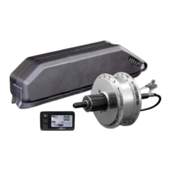
/ Entladung / Wartung nicht möglich ist, kann ANSMANN keinerlei Haf- tung für Verluste, Schäden oder Kosten übernehmen. Jeglicher Anspruch auf Schadensersatz, der durch den Betrieb, den Ausfall bzw. Fehlfunktio- nen ergeben kann, oder in irgendeiner Weise damit zusammenhängt, wird abgelehnt. - Page 8 ORIGINALBETRIEBSANLEITUNG - ELEKTRO-ANTRIEB FÜR PEDELECS LI-ION RAHMENAKKU 36V 10INR18/65-5 mit Kapazitätsanzeige, Ladebuchse und Schloss (Diebstahlschutz), Akkuhalter zur Befestigung an Unterrohr (inklusive Befestigungsmaterial) mit Kabelverbindung zu Motorcontroller Box zur Unterbringung des Motorcontrollers (z.B. zur Befestigung am Sattelrohr) ODER LI-ION FLACHAKKU 36V 10INR18/65-4 mit Kapazi- tätsanzeige und Ladebuchse, Akkuschacht mit Schloss (Diebstahlschutz) und Controllerbox angebaut an Gepäckträger...
-
Page 9: Montage Des Motors
Die Länge der Bremsscheibenschrauben ist so zu wählen, dass sie maximal 8mm in das Motorgehäuse eingeschraubt werden können. Bei Nichtbeachtung können Schäden am Motor entste- hen. Beim Anzugsmoment der Bremsscheibenschrauben richten Sie sich bitte an die Angaben des Herstellers. www.ansmann.de... - Page 10 ORIGINALBETRIEBSANLEITUNG - ELEKTRO-ANTRIEB FÜR PEDELECS Länge der Bremsscheiben- schrauben und Anzugsmoment beachten NUR BEI HINTERRADMOTOR RM5.0 Bevor das Motorlaufrad am Fahrrad montiert werden kann, muss eine Steckkassette (Ritzelpaket) ordnungsgemäß montiert sein. Beim Anzugsmoment für die Steckkassette richten Sie sich bitte an die Angaben des Herstellers. Bei der Befestigung des Laufrades ist darauf zu achten, dass das Formteil der Drehmomentabstützungen (beidseitig) nach unten gedreht ist, damit die Achse passend in Gabel (Vorderradmotor) / Ausfallende (Hinterradmo-...
-
Page 11: Montage Des Akkuhalters Für Unterrohrakku
Montage des Halters an der Halterunterseite an den vorgese- henen Stellen anzukleben. Um einen festen Sitz des Halters zu garantieren und Schäden am Halter zu vermeiden ist der Abstand zwischen den Flaschenhal- terverschraubungen und dem Akkuhalter durch Einbringen von Beilagscheiben zu reduzieren (siehe Abbildung). www.ansmann.de... -
Page 12: Montage Des Gepäckträgers Für Flachakku
ORIGINALBETRIEBSANLEITUNG - ELEKTRO-ANTRIEB FÜR PEDELECS Anzugsmoment: 1Nm 10. AKKUHALTER GEPÄCKTRÄGERAKKU Der Akkuhalter (-schacht) für den Flachakku und die Box für den Motorcon- troller ist ab Werk bereits am Gepäckträger montiert. Am Schacht befin- det sich ein Verbindungskabel für den Anschluss am Motorcontroller. Der Gepäckträger ist am Rahmen an den vorgesehenen Stellen zu befestigen. -
Page 13: Verwendung Akku/Ladegerät
Akkus am Rad verriegelt sich der Akku selbst (Diebstahlschutz), sobald der Akku komplett auf den Halter aufgeschoben ist (Schlüssel zum Verriegeln nicht notwendig). Öffnen Sie zum Laden mit Hilfe der Verschlusskappe (3) den Zugang zur Ladebuchse (4) und schließen Sie dort den Ladestecker (5) des Ladege- rätes an. www.ansmann.de... - Page 14 ORIGINALBETRIEBSANLEITUNG - ELEKTRO-ANTRIEB FÜR PEDELECS Bei dem Flachakku drehen Sie den Schlüssel entgegen dem Uhrzeiger- sinn (1.), danach schieben sie den Akku nach hinten aus seiner Halterung (2.). Nach dem erneuten Einschieben des Akkus in den Akkuschacht müs- sen Sie den Akku über das Schloss verriegeln (Schlüssel in Uhrzeigersinn drehen) um ihn gegen Herausfallen zu sichern (auch Diebstahlschutz).
- Page 15 Zellen enthalten Lithium Li-ion Der Akku darf nicht über den Hausmüll entsorgt werden ¡ Verwenden Sie ausschließlich ein für diesen Akku vorgesehenes Ladegerät von ANSMANN ¡ Vermeiden Sie Kurzschlüsse ¡ Akku beim Laden auf nicht brennbare, hitzebeständige Unterla- ge legen. Es dürfen sich keine brennbaren oder leicht entzündli- che Gegenstände in der Nähe des Akkus befinden...
-
Page 16: Verkabelung
ORIGINALBETRIEBSANLEITUNG - ELEKTRO-ANTRIEB FÜR PEDELECS ¡ Akkus sind kein Spielzeug. Von Kindern fernhalten! ¡ Originalstecker und –kabel dürfen nicht abgeschnitten oder ver- ändert werden Fehlbehandlungen führen zu Risiken wie Explosion, Überhitzung oder Feuer. Nichtbeachtung der Verwendungshinweise führt zu vorzeitigem Verschleiß oder sonstigen Defekten. Diese Anleitung ist sicher aufzubewahren und im Falle einer Weitergabe des Ak- kus dem nachfolgenden Benutzer unbedingt mitzugeben. - Page 17 Kontaktierung auszuschließen. Das Steuergerät und Kabelüberlängen sind dann in der Controllerbox zu verstauen. Optional kann am Anschluss L3 (PO- WER) ein Lichtmodul angeschlossen werden. www.ansmann.de...
-
Page 18: Inbetriebnahme
ORIGINALBETRIEBSANLEITUNG - ELEKTRO-ANTRIEB FÜR PEDELECS 13. INBETRIEBNAHME Sobald der Akku Ladung hat und fest auf dem Halter / im Akkuschacht auf- / eingeschoben ist, ist das Antriebssystem betriebsbereit. 13.1 EIN- / AUSSCHALTEN Bei Verwendung eines Unterrohrakkus erfolgt das Einschalten des An- triebssystems durch kurzes Drücken der Taste an der Kapazitätsanzeige am Akku ( Einschaltung wenige Sekunden nach Tastendruck). -
Page 19: Bedienung Led Display
Sofern der Antrieb mit einem LCD Display ausgeliefert wurde, erfolgt die Be- dienung des Antriebs hierüber. Das LCD Display ist zusätzlich mit Tachome- terfunktionen ausgestattet. Die Steuerung der Fahrstufen und die Abfrage der Tachometerfunktionen er- folgt über die 3 Bedientasten. www.ansmann.de... - Page 20 ORIGINALBETRIEBSANLEITUNG - ELEKTRO-ANTRIEB FÜR PEDELECS Anzeige Hintergrundbeleuchtung Anzeige Tachometerfunktion Abfrage Tachometer- funktionen Einstellung Fahrstufe Hintergrundbeleuchtung Einstellung Fahrstufe Schiebehilfe Anzeige Fahrstufe Akkufüllstand Direkt nach dem Einschalten des Antriebs über die Taste / den Schalter am Akku wird über die Displaysteuerung automatisch die Fahrstufe 2 eingestellt. Mit den Tasten “...
-
Page 21: Fahrradbeleuchtung (Optional)
14. FAHRRADBELEUCHTUNG (OPTIONAL) Wie bereits im Abschnitt 12. VERKABELUNG beschrieben, ist das Antriebssys- tem schon für den Anschluss eines Lichtmoduls vorbereitet. Das ANSMANN Lichtmodul besitzt hierfür schon die korrekte Steckverbindung. Am Lichtmo- dul selbst können dann sowohl der Frontscheinwerfer als auch das Rücklicht direkt angeschlossen werden. -
Page 22: Motorunterstützung
ORIGINALBETRIEBSANLEITUNG - ELEKTRO-ANTRIEB FÜR PEDELECS Der Anschluss L3 ist solange stromführend, solange der Akku eingeschaltet ist. Eventuell Licht gesondert ein-/ausschalten. 15. MOTORUNTERSTÜTZUNG Mit dem Einschalten des Antriebssystems über den Akku ist dieses be- triebsbereit. Die Fahrstufe 2 ist bereits vorgewählt, kann aber jederzeit (auch vor Fahrtbeginn) verändert werden. -
Page 23: Technische Daten
250Watt (Nenndauerleistung) Leistung 400Watt (Spitzenleistung) Motorunterstützung in 6 Stufen bis max. 25km/h Steuerung Schiebehilfe bis max. 6km/h Drehmoment bis zu 30Nm FM4.0 ca. 1.8kg Gewicht RM5.0 ca. 2.0kg AKKU Lithium-Ion Akkupack Modell 10INR18/65-4 oder 10INR18/65-5 Kapazität je nach Modell 9.0Ah (324Wh) – 17.5Ah (630Wh) -
Page 24: Zubehör / Ersatzteile
42Volt DC, 1.4A oder 2.35A 17. ZUBEHÖR / ERSATZTEILE Um die Betriebssicherheit zu gewährleisten verwenden Sie bitte ausschließ- lich Zubehör und Ersatzteile von ANSMANN, die hierfür vorgesehen sind. Im Lieferumfang befindlichen Teile können bei Verschleiß oder Verlust als Ersatzteile bezogen werden. -
Page 25: Eg-Einbauerklärung
Konto-Nr. 0030055101 BLZ66069342 Swift: GENODE61KTH 97959 Assamstadt Sparkasse Tauberfranken Konto-Nr. 0006082010 BLZ 67352565 Swift: SOLADES1TBB Telefon 06294/4204-0 Aufsichtsratsvorsitzender: Edgar Ansmann BW-Bank Konto-Nr. 0004110714 BLZ 60050101 Swift: SOLADEST 06294/4204–4400 Reg. Amtsgericht Ulm HRB B721168 Deutsche Bank Konto-Nr. 0120077300 BLZ 62070081 Swift: DEUTDESS620 E-Mail: info@ansmann.de... -
Page 26: Preface
ORIGINAL OPERATING INSTRUCTIONS - ELECTRIC DRIVE FOR PEDELECS 1. PREFACE Dear Customer, THANK YOU FOR CHOOSING AN ELECTRIC DRIVE FROM ANSMANN. These instructions are intended to help you install and use this drive. By using this drive, you are choosing a future-oriented and environmentally friendly means of transport. -
Page 27: Table Of Contents
13.1 Switching ON / OFF ................. 42 13.2 Operation LED display ................43 13.3 Operation LCD display ................43 Bicycle lighting (optional) ..............45 Motor assist .................... 46 Technical data ..................47 Accessories / spare parts ..............48 Declaration of incorporation ..............49 www.ansmann.de... -
Page 28: Legal Foundation
ORIGINAL OPERATING INSTRUCTIONS - ELECTRIC DRIVE FOR PEDELECS 3. LEGAL FOUNDATION This electric drive turns your bicycle into an Electrically Power Assisted Cycle (EPAC). Another term for this type of bicycle is a pedelec (a composite term derived from pedal, electrical and cycle), which describes a special type of electrical bicycle where an auxiliary drive only works in tandem with the pedal drive. -
Page 29: General Assurance
5. GENERAL ASSURANCE ANSMANN grants a legal warranty for manufacturing or material defects existing at the point of delivery, restricted to the parts delivered by ANS- MANN. This legal warranty is not valid for defects caused by improper hand- ling, a lack of maintenance, external impacts or mechanical damage. -
Page 30: Disclaimer Of Liability
As it is not possible to control the handling, that all assembling rules and- operating instructions are obeyed and also the impossibility to maintenan- ce the battery and it’s charging / discharging, ANSMANN in not able to take any liability for losses, damages or costs. Any claim of compensation which can be caused by the use, defaults or malfunctions, or is connected to it in any way, will be refused. -
Page 31: Components Of The Electric Drive
7. COMPONENTS OF THE ELECTRIC DRIVE SCOPE OF DELIVERY: FRONT WHEEL MOTOR FM4.0 36V / 250W for bicy- cle forks with dimensions of 100mm, include axis assembling parts and motor extension wire, possibility for brake disc assembling. REAR WHEEL MOTOR RM5.0 36V / 250W for... - Page 32 MOTOR CONTROLLER 36V / 12A PEDAL SENSOR SET with magnetplate(s) BRAKE LEVERS for mechanical brakes include motor stop switches BATTERY CHARGER 36V 1.4A (OR 36V 2.35A) for ANSMANN pedelec batteries CABLE TIES for fixing the cables at the bicycle frame...
-
Page 33: Installing The Motor
For the tightening torque of the brake disc screws, follow the manufacturer’s specifications. Observe length of the brake disc screws and tightening torque ONLY AT REAR WHEEL MOTOR RM5.0 Before the motor impeller can be assembled into a bicycle, a www.ansmann.de... - Page 34 ORIGINAL OPERATING INSTRUCTIONS - ELECTRIC DRIVE FOR PEDELECS cassette (sprocket set) has to be properly assembled. For the tightening torque of the cassette, please follow the manufac- turer’s specifications. When fastening the impeller, make sure the moulded part of the torque supports (both side) is turned downwards, that the axis fits correctly inside the fork (front wheel motor) / back end (rear wheel motor).
-
Page 35: Installing The Battery Holder For Down Tube Battery
To ensure that the holder sits securely and prevent it from get- ting damaged, reduce the distance between the bottle holder fittings and the battery holder by adding washers. tightening torque: 1Nm www.ansmann.de... -
Page 36: Installing The Carrier For The Flat Battery
ORIGINAL OPERATING INSTRUCTIONS - ELECTRIC DRIVE FOR PEDELECS HOLDER FOR THE CARRIER BATTERY The holder (battery case) for the flat battery and the box for the motor controller is factory-equipped assembled with the carrier. At the battery case the connecting cable for the connection to the motor controller is already assembled. - Page 37 (1.), then push the battery out of its case (2.). After the battery is assembled into the case again it need to be locked with the key (turning the key clockwise) that the battery could not fall out during riding (also for theft deterrence). www.ansmann.de...
- Page 38 ORIGINAL OPERATING INSTRUCTIONS - ELECTRIC DRIVE FOR PEDELECS To charge the battery, open the cap (3) on the charging socket (4) and connect the plug (5) from the charger. Once you have connected the charger to the battery, connect the charger to the mains outlet with the power plug.
- Page 39 European standards Cells contain lithium Li-ion The battery must not be disposed of in household waste ¡ To charge the battery, use only a charger from ANSMANN designed for this battery. ¡ Avoid short-circuits. ¡ Place the battery on a non-combustible, heat-resistant surface when charging it.
-
Page 40: Wiring
ORIGINAL OPERATING INSTRUCTIONS - ELECTRIC DRIVE FOR PEDELECS Incorrect handling leads to risk such as explosion, overheating or fire. Failure to observe the instruction for use will lead to pre- mature wear or other defects. Keep these instructions in a safe place and be sure to include them if you give the battery to ano- ther user. - Page 41 www.ansmann.de...
-
Page 42: Start-Up
ORIGINAL OPERATING INSTRUCTIONS - ELECTRIC DRIVE FOR PEDELECS 13. START-UP As soon as the battery is charged and firmly latched in the holder, the drive system is ready for use. 13.1 SWITCHING ON / OFF When using a down tube battery you switch ON the electric drive by short pressing the button on the capacity indicator of the battery ( few se- conds after you pressed the button display show drive is ON ). -
Page 43: Operation Led Display
If the electric drive was delivered together with a LCD display the drive fun- ctions would be adjusted by this display. The LCD display is equipped with additional speedometer functions. The selection of assist levels and the speedometer functions will be done by the 3 buttons. www.ansmann.de... - Page 44 ORIGINAL OPERATING INSTRUCTIONS - ELECTRIC DRIVE FOR PEDELECS backlight indicator speedometer functions indicator query the speedo-meter functions assist level selection backlight assist level selection pushing aid motor assist level battery level When the electric drive was switched ON at the battery the motor assist level 2 is automatically preselected.
-
Page 45: Bicycle Lighting (Optional)
14. BICYCLE LIGHTING (OPTIONAL) As already described under 12. WIRING, the electric drive is already prepared for the connection of an ANSMANN light module. This ANSMANN light module has the correct connector to connect it to the control unit. At the light mo- dule it will be possible to connect the headlights and the rear light directly. -
Page 46: Motor Assist
ORIGINAL OPERATING INSTRUCTIONS - ELECTRIC DRIVE FOR PEDELECS 15. MOTOR ASSIST By switching ON the electric drive via the battery the system is operational. The assist level 2 is already preselected, but may be changed at any time (even before cycling). Due to legal restrictions, the motor will assist you only during pedaling. -
Page 47: Technical Data
250W (nominal continuous power) Power 400W (peak power) 6 motor assist level up to 25km/h Control Pushing aid function up to 6km/h Torque up to 30Nm FM4.0 approx. 1.8kg Weight RM5.0 approx. 2.0kg BATTERY Lithium-Ion battery Model 10INR18/65-4 or 10INR18/65-5 Capacity from 9.0Ah (324Wh) to 17.5Ah (630Wh) -
Page 48: Accessories / Spare Parts
ORIGINAL OPERATING INSTRUCTIONS - ELECTRIC DRIVE FOR PEDELECS 17. ACCESSORIES / SPARE PARTS To ensure operating safety and reliability, please only use ANSMANN acces- sories and spare parts intended for this purpose. The parts that are already in the scope of delivery can be purchased as spare parts in the event of wear or loss. -
Page 49: Declaration Of Incorporation
Konto-Nr. 0030055101 BLZ66069342 Swift: GENODE61KTH 97959 Assamstadt Sparkasse Tauberfranken Konto-Nr. 0006082010 BLZ 67352565 Swift: SOLADES1TBB Telefon 06294/4204-0 Aufsichtsratsvorsitzender: Edgar Ansmann BW-Bank Konto-Nr. 0004110714 BLZ 60050101 Swift: SOLADEST 06294/4204–4400 Reg. Amtsgericht Ulm HRB B721168 Deutsche Bank Konto-Nr. 0120077300 BLZ 62070081 Swift: DEUTDESS620 E-Mail: info@ansmann.de... -
Page 50: Prefazione
MANUALE D’USO - KIT ELETTRICI PER EBIKE 1. PREFAZIONE Gentile Cliente, GRAZIE PER AVER SCELTO UN SISTEMA ANSMANN. Le seguenti istruzioni hanno la finalità di assisterti nell’installazione e uti- lizzo del sistema. Scegliendo questo sistema hai scelto un mezzo di tras- porto orientato al futuro e rispettoso dell’ambiente. -
Page 51: Contenuti
Start-up ....................67 13.1 Accensione/Spegnimento ON/OFF ............67 13.2 Display LED ....................68 13.3 Display LCD ....................68 Illiminazione (opzionale) ................ 70 Assistenza motore ................. 71 Dati tecnici ....................72 Accessori / parti di ricambio..............73 Dichiarazione ..................74 www.ansmann.de... -
Page 52: Informazioni Legali
Ansmann deve essere conforme alla normativa EN14764 (per city bike e trekking) e EN 14766 (per mountain bike). Una volta che il Sistema Ansmann è installato in modo appropriato secondo manuale su di un bicicletta che risponde alle norme su citate, la bicicletta automaticamente è... -
Page 53: Assicurazione Generale
AAnsmann garantisce la garanzia legale per difetti di produzione o di ma- teriale fino al luogo di consegna, limitatamente alle parti consegnate da Ansmann. Tale garanzia legale non è valida in caso di difetti causati da uso improprio, mancanza di manutenzione, danni meccanici o dovuti a impatti esterni. -
Page 54: Dichiarazione Di Non Responsabilità
è possibile controllare come la batteria viene caricata/scaricata e stoccata, ANSMANN non si assume nessuna respons- abilità in caso di perdite, danni o costi. Qualsiasi reclamo di compensazione collegato all’uso errato, errori o malfunzionamenti sarà... -
Page 55: Componenti Del Sistema
7. COMPONENTI DEL SISTEMA ELETTRICO CONPONENTI CONSEGNATE: MOTORE FRONTALE FM4.0 36V/250W per forcelle misura 100mm, incluse parti di assemblaggio asse e cavo motore, possibile assemblaggio freni a disco. OPPURE MOTORE POSTERIORE RM5.0 36V/ 250W per telai mis. Posteriore 135mm, incluse parti di assem- blaggio asse e cavo motore, fino a 10 velocità... - Page 56 MANUALE D’USO - KIT ELETTRICI PER EBIKE BATTERIA PIATTA 36V 10INR18/65-4 con capacità di taratura/calibratura, presa di carica, housing con lucchetto di sicurezza e scatola per centralina/controller, entrambe da assemblare nel portapacchi fornito in dotazione con il kit DISPLAY LED CON TASTI per controllo del motore, posizionamento su manubrio, visualizzazione livello di carica batteria e selezione del livello di assistenza...
-
Page 57: Installazione Del Motore
CARICATORE ORIGINALE ANSMANN per batteria 36V 1.4A (oppure 36V 2.35A) FASCETTE DI FISSAGGIO dei cavi al talaio MANUALE D’USO 8. ASSAMBLAGGIO DEL MOTORE Il motore deve essere fissato in un rotore/girante della misura corrispon- dente come previsto dalla normativa. A tale scopo, devono essere utilizzati cerchi a 36 fori approvati per l’uso su pedelec. - Page 58 MANUALE D’USO - KIT ELETTRICI PER EBIKE Osservare la lunghezza delle viti del freno a disco e la loro torsione di fissaggio SOLO PER IL MOTORE POSTERIORE RM5.0 Prima di assemblare il rotore del motore sulla bici, la cassetta (la ruota dentata) deve essere correttamente assemblata. Per la torsione di fissaggio della cassetta seguire le istruzioni del produttore.
-
Page 59: Borraccia)
Il supporto/piastra è fissato con degli attacchi su tubo porta borraccia della bicicletta. Le viti svasate Tx25 M5x20 sono incluse. Prima di assemblare la piastra di supporto, fissa- re gli spessori di gomma inclusi sul telaio e sotto della piastra. www.ansmann.de... -
Page 60: Installazione Del Portapacchi Per La Batteria A Portapacchi
MANUALE D’USO - KIT ELETTRICI PER EBIKE Per assicurarsi che la piastra di supporto sia ben fissata e per evitare che si possa danneggiare, ridurre la distanza tra il telaio e la piastra aggiungendo delle rondelle/guarnizioni. Torsione di fissaggio: 1Nm SUPPORTO PER LA BATTERIA A PORTAPACCHI Il supporto (housing della batteria) della batteria piatta a portapacchi e la... -
Page 61: Uso Della Batteria E Del Caricatore
Per rimuovere la batteria down tube girare la chiave in senso orario (1), spingere la batteria fuori dal suo supporto (2). Quando la batteria viene assemblata sulla bici e inserita nella piastra di supporto, la batteria si blocca automaticamente (deterrente) e quindi non serve girare la chiave di sicurezza! www.ansmann.de... - Page 62 MANUALE D’USO - KIT ELETTRICI PER EBIKE Per ricaricare la batteria aprire il tappo (3) che copre la presa (4) e connet- tere il caricatore (5). Per rimuovere la batteria a portapacchi della bicicletta, aprire anzitutto la chiavi di bloccaggio girandola in senso anti-orario (1), poi spingere la batteria fuori dal suo involucro (casing/housing).
- Page 63 Raccomandiamo di ricaricare la batteria dopo ogni suo utilizzo. Se la batte- ria non viene utilizzata per un periodo lungo (per esempio durante l’inverno) caricarla completamente prima di depositarla. Per evitare danni alla batte- ria, ricaricarla ogni 12 settimane. Stoccare in un luogo asciutto e rispettare le temperature indicate. www.ansmann.de...
- Page 64 Li-ion Non smaltire tra I rifiuti domestici. Smaltire presso punti di rac- colta autorizzati ¡ Per caricare la batteria utilizzare solo caricatori originali Ansmann ¡ Evitare corti-circuiti ¡ Durante la ricarica posizionare la batteria su superifici non com- bustibili e resistenti al calore. Nell’area circostante non ci de- vono essere oggetti infiammabili o combistibili ¡...
-
Page 65: Cablaggi
¡ I cavi e le presi originali Ansmann non devono essere tagliati o modificati in nessun caso! Un’ utilizzo sbagliato può provocare rischio di esplosione, sur- riscaldamento o fuoco. Un’ utilizzo errato e non conforme al manuale d’istruzioni può provocare difettosità o usura precoce. - Page 66 MANUALE D’USO - KIT ELETTRICI PER EBIKE La centralina e tutti i cavi vanno poi custoditi all’interno della scatola della centralina. Opzionale: il modulo luce può essere connesso al terminale L3 (potenza).
-
Page 67: Start-Up
è inferiore a 100mA). Nel caso di batteria a portapacchi, per accendere il Sistema usare il tasto di accensione ON/OFF della batteria. Per spegnere il sistema premere il tasto OFF sulla batteria. ON / OFF www.ansmann.de... -
Page 68: Display Led
MANUALE D’USO - KIT ELETTRICI PER EBIKE 13.2 DISPLAY LED Se è stato conseganto il display LED con il Sistema, le funzioni di guida sono selezionabili dal questo display. Nel display sono presenti i led di segnale del livello di carica della batteria e del livello di assistenza del motore. - Page 69 Premen- do velocemente il tasto ‘’M’’ è possibile selezionare le funzioni tachimetro: VELOCITA’, VELOCITA’ MEDIA, VELOCITA’ MASSIMA, CONTACHILOMETRI, DISTANZA, TEMPO DI VIAGGIO. Quando il sistema viene acceso la velocità è preselezionata automaticamente. www.ansmann.de...
-
Page 70: Illiminazione (Opzionale)
14. LUCI (OPZIONALE) Come già descritto al paragrafo 12. CONNESSIONI, il Sistema è predisposto per l’utilizzo del modulo luce Ansmann. Questo modulo luce ha già i connettori predisposti per la connessione alla centralina. E’ possibile collegare poi al modulo luce le luci anteriore e posteriore direttamente. -
Page 71: Assistenza Motore
Grazie alla ruota libera del motore è possibile utilizzare la bicicletta con il Sistema elettrico (pedelec) come una normale bicicletta, cioè senza la batteria o con la batteria spenta. Una forza maggiore durante la pedalata non è necessaria. www.ansmann.de... -
Page 72: Dati Tecnici
250W (Potenza nominale continua) Potenza 400W (Potenza di picco) 6 livelli di assistenza fino a max 25km/h Controllo assistenza iniziale fino a 6km/h Torsione fino a 30Nm FM4.0 approx. 1.8kg Peso RM5.0 approx. 2.0kg BATTERIA Lithium-Ion battery Modello 10INR18/65-4 or 10INR18/65-5 Capacità... -
Page 73: Accessori/Parti Di Ricambio
Ansmanm intesi per questo utilizzo. Tutti gli accessori e parti necessarie sono incluse nel sistema elettrico Ansmann. Tutte le parti di ricambio possono essere ac- quistate successivamente in caso di usura o perdite. -
Page 74: Dichiarazione
Konto-Nr. 0030055101 BLZ66069342 Swift: GENODE61KTH 97959 Assamstadt Sparkasse Tauberfranken Konto-Nr. 0006082010 BLZ 67352565 Swift: SOLADES1TBB Telefon 06294/4204-0 Aufsichtsratsvorsitzender: Edgar Ansmann BW-Bank Konto-Nr. 0004110714 BLZ 60050101 Swift: SOLADEST 06294/4204–4400 Reg. Amtsgericht Ulm HRB B721168 Deutsche Bank Konto-Nr. 0120077300 BLZ 62070081 Swift: DEUTDESS620 E-Mail: info@ansmann.de... - Page 75 NOTIZEN | NOTES www.ansmann.de...
- Page 76 97959 Assamstadt GERMANY info@ansmann.de | www.ansmann.de Art. Nr.: 0120-3026 • 08/2016 • Änderungen vorbehalten • Keine Haftung für Irrtümer und Druckfehler. • Subject to modifications • No liability for errors and misprints.• Soggetto a modifiche senza obbligo di preavviso • Nessuna responsabilità...
Need help?
Do you have a question about the FM4.0 and is the answer not in the manual?
Questions and answers