
Related Manuals for AMPLITUDE SCORE

Summary of Contents for AMPLITUDE SCORE
- Page 1 Surgical Technique With Navigation 4-in-1 Instrumentation SCORE / SCORE ® ® Primary Total Knee System Mobile bearing...
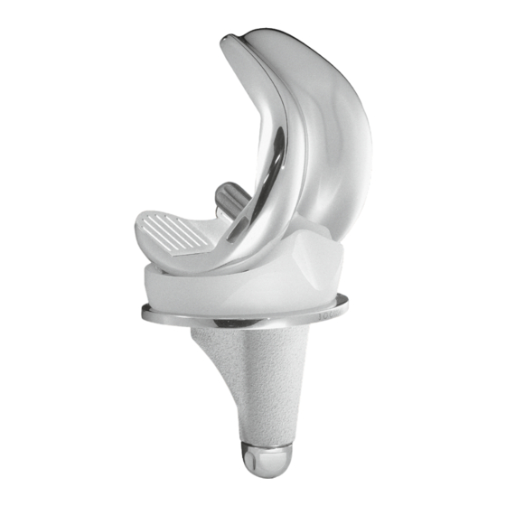
- Page 2 Overview of SCORE / SCORE AS TKS ® ® • The SCORE TKS is a PCL-sacrificing, mobile bearing implant in rotation for primary knee ® arthroplasty. • The stability is provided by sagittal and frontal congruency through the extension to the flexion.
- Page 3 Overview of SCORE / SCORE AS TKS ® ® 1. Femoral component: Component in Cobalt Chrome. Anterior cut at 6° Dual coated cementless component (80 μm plasma- sprayed titanium + 80 μm HAP). Cemented* component is micro-blasted. * SCORE AS femoral component in Cobalt ®...
- Page 4 Overview of SCORE ® The polyethylene patellar implant are available in three versions: Resurfacing patella Inserted patella Inserted patella with cement cemented cementless Thickness: Thickness: Thickness: 8 mm 7 mm 8,5 mm 2. Tibial component: Rotative mobility of the tibial insert:...
- Page 5 Overview of SCORE ® Tibial baseplate: Anatomical posterior shape Mirror polish finish contact surface with mobile insert Anatomical coverage in rotation (mobile insert) 3 sizes of delta wings (sizes 1-2, 3-4-5, 6-7) Conical tibial keel Component in Cobalt Chrome. shape identical for all...
- Page 6 Overview of SCORE ® 3. SCORE implant product range: ® • Femoral components: - Cemented condyles: 7 sizes - Uncemented condyles: 7 sizes Δ AP: increment between sizes: 2.66 mm Δ ML: increment between sizes: 3.3 mm • Patellar components: - Resurfacing patella with cement: Ø...
- Page 7 Overview of SCORE ® 4. Components compatibility: Femoral component & insert size Tibial baseplate size The SCORE femoral implant is compatible with the whole range of patellar implants. ®...
-
Page 8: Workstation Components
Workstation components Front: Status lights Laser pointer Optical sensors Camera head positioning handles Laser control buttons Carry handles (bilateral) (both sides) Speakers (both sides) LCD touch screen USB ports V2 Workstation Optical sensors Laser pointer Status lights Camera head positioning handles USB ports Carry handles (both sides) - Page 9 Workstation components Rear: Camera head Tower locking handles tightening knobs Camera head release button Power cord holder Vent Rear ports Power cord alimentation On/Off switch V2 Workstation Tower unlocking handle Vent Power cord holder Rear ports V3 Workstation...
-
Page 10: Preparation Phase
Preparation phase Storage area for pedal and workstation cover Front Rear Latch Shipping case for V2 Workstation Storage area for pedal and workstation cover Rear Front Latch Shipping trunk for V3 Workstation Pedals for V2 Workstation Pedals for V3 Workstation... - Page 11 Preparation phase • Unlock the four latches on the shipping trunk. • Open the front panel and take out the workstation, pedal and pedal cover. • Place the workstation on a stable table or operating room cart. • Clean the workstation according to the instructions in the user manual or in the software. NOTE: - The workstation user manual is found in the shipping trunk.
- Page 12 Preparation phase Locked position Locking lever Unlocked position...
- Page 13 Preparation phase • Position the workstation so that it is at least 1.5 m from the patient. • Set the camera head in neutral position (maximum height, no rotation). • Unlock the adjustable tower: lift the locking lever and let the tower rise freely until it reaches its maximum height.
-
Page 14: Screen Layout
Screen layout Title of current step Screenshot capture button Information area and Active area buttons Yellow pedal: indicates action Blue pedal: action carried out when Menu: carried out when pedal is pressed pedal is pressed Options Visibility of each array: Indicates if pointer Green - visible... - Page 15 Options menu description The «Exit Application» button will only be active during the final step. To exit the application before the final step, go to the «Options» menu to select it. Show camera field of view to locate arrays View all the validated steps Reset navigation station position during the surgery relative to surgeon position...
- Page 17 Preparation phase • Press the touch screen to select the preferred system language. • Select «Knee», then select the ANATOMIC implant and the 4-in-1 protocol. ® • On the «Information» page, input the required information using the virtual keyboard. - Surgeon name - Patient name - Patient date of birth (optional) - Operated side (select right or left)
- Page 18 Marker Spherical Release button Markers Array Array fixation support Fixation pins Femur Femur array Tibia array Fixation pins...
- Page 19 Preparation phase • Clip the round markers to the arrays: - 3 for the Tibia (T) array - 3 for the Femur (F) array - 4 for the Pointer (P) array - 3 for the Guide (G) array • The pins must be placed on the anteromedial side of the femur and tibia (when the surgeon stands on the lateral side) and must not interfere with tap placement.
- Page 20 3D view of arrays...
-
Page 21: Workstation Setup
Workstation setup Setting up the camera: • Position the camera head so the letters corresponding to the F and T arrays are in the middle of the field of view. The laser located in the positioning handles on the camera head (V2 Workstation) or between the two optical sensors (V3 Workstation) makes this adjustment easier. - Page 23 Calibrating the pointer and arrays Calibrating the pointer: To define exactly the position of the pointer tip, • Calibrate the pointer by placing its tip in the conical calibration mark on one arm of the T array and press trigger to confirm. •...
- Page 25 Ankle centre acquisition Medial malleolus: • Place the pointer tip on the most medial point of the medial malleolus. • Press the trigger on the pointer to confirm. Lateral malleolus: • Place the pointer tip on the most lateral point of the lateral malleolus. •...
- Page 27 Coordinate reference system: Tibial acquisition Centre of the tibia: • Place the pointer tip on the middle of the intercondylar eminence on the axis of the tibial shaft. • Press the trigger to confirm. Tibial sagittal axis: • Place the pointer tip on the intercondylar eminence and turn the body of the pointer. •...
- Page 29 Tibial acquisition The goal of this step is to acquire the tibial bone surface and then verify its accuracy. • The acquisition process is initiated by pressing the trigger on the pointer and ends when the trigger is released. The system will beep to indicate the start and end of the acquisition. •...
- Page 31 Tibial planning Reference point for tibial resection height: • Select and acquire the reference point that will be used to define the resection height, e.g. a point on the healthy side. • Use the information from the heat map showing the healthiest areas (highest points) in green tints and the most worn areas (lowest points) in red tints.
- Page 33 Acquisition fémorale Top of intercondylar notch: • Place the pointer tip at the top of the femur’s intercondylar notch and along the femoral shaft axis, then confirm. Medial and lateral posterior condyles: • Place the pointer tip at the top of the medial posterior condyle and validate; do the same for the top of the lateral posterior condyle.
- Page 35 Femoral acquisition Digitisation of femoral articular surface The goals of this step are to acquire the femoral bone surface and verify its accuracy. • Place the pointer tip on the bone surface. Press and hold trigger then move the tip along the surface being acquired.
- Page 37 Femoral acquisition Measuring the pre-operative HKA angle: • Extend the leg so that there is no load on it. • View the pre-operative HKA angle. • An initial estimate of joint laxity will be displayed (projection of points acquired on tibial articular surfaces onto the femur).
- Page 38 Semi-assisted resection guide Universal Alignment Guide TIBIAL CUT NAVIGATION...
- Page 39 Tibial cut guiding and acquisition This step consists of two functions: - Navigation of tibial resection plane. - Acquisition of the cut. Tibial cut guiding: This step can be performed using either: - the universal alignment guide, or - the semi-assisted resection guide. If using the universal alignment guide: •...
- Page 40 TIBIAL CUT ACQUISITION Universal Alignment Guide...
- Page 41 Tibial cut guiding and acquisition Tibial cut acquisition: This step is performed with the universal alignment guide. • Place the universal alignment guide (with the G array on it) on the tibial cut and confirm this step to acquire the cut.
- Page 42 Semi-assisted resection guide Universal Alignment Guide DISTAL CUT NAVIGATION...
- Page 43 Distal cut guiding and acquisition This step consists of two functions: - Navigation of distal resection plane. - Acquisition of the cut. Distal cut guiding: This step can be performed using either: - the universal alignment guide, or - the semi-assisted resection guide. If using the universal alignment guide: •...
- Page 44 DISTAL CUT ACQUISITION Universal Alignment Guide...
- Page 45 Distal cut guiding and acquisition Distal cut acquisition: This step is performed with the universal alignment guide. • Place the universal alignment guide (with the G array on it) on the distal cut and confirm this step to acquire the cut.
- Page 47 Management of extension gaps • Extend the knee so that it is as close as possible to the value shown in parentheses on the screen. NOTE: For example, if the tibial cut has a 2° posterior slope and the distal femoral cut is in 1° flexion, then the leg needs to be placed in 3°...
- Page 49 Management of flexion gaps • Flex the knee so that it is as close as possible to the value shown in parentheses (see explanation on page 47). • Place tension on the ligaments and evaluate the medial and lateral gaps between the tibial cut and the virtual femoral component.
- Page 51 Gap management Display options Whiteside’s line: Press the button in the middle lower portion of the screen. The original Whiteside’s line is shown in white, along with the trochlea’s axial rotation. The implant’s Whiteside’s line is shown in blue. Gaps without the virtual implants: Go to the «...
- Page 52 Possibility of a central pin...
- Page 53 In patients with osteoporosis, better fixation can be achieved by adding a pin in the intercondylar notch, connect the two handles on the cutting guide for better hold while inserting the pins. • Make the anterior and posterior cuts using a medium AMPLITUDE saw blade that matches the ® instrumentation set and motorized handpiece.
- Page 55 Placement of trial femoral component • Select the trial femoral component of the same size as the 4-in-1 resection guide used in the previous steps (the planned size is shown on the upper part of the screen) and of the same operated side.
- Page 57 Placement of trial tibial component • Select the appropriate tibial baseplate (the planned size is shown on the screen) and secure it to the baseplate handle. • Assemble the universal handle with the trial baseplate. • Position and secure the trial baseplate with two, 30-mm long headed pins. •...
- Page 59 Trial implants In extension: • Install a trial insert of the same thickness as the gaps shown during ligament balancing. • Extend the leg. • The HKA angle, and medial and lateral gaps with the trial components in place will be displayed. In flexion: •...
- Page 61 Tibial plateau preparation Important: remove the 2 headless pins left in the tibia. • Position the appropriate sized routing guide onto the trial baseplate. • Ream using the tibial reamer to the stop(same for all sizes). • Impact the appropriate sized tibial stem punch. (In case of a sclerotic bone or after osteotomy, prepare first with an osteotome).
- Page 63 Patellar preparation Patellar resection option After clearing the area around the patella, • Place the clamp so the two lugs are on the anterior side of the patella. • With the clamp jaws open, bring the 8 mm probe into contact with the articular surface using the adjustment knob.
- Page 65 Placing definitive implants • On the selected tibial baseplate (with or without cement), tighten the stem or, if required, the extension stem using the wrench. • Position the baseplate with the tibial baseplate impactor. • Place the polyethylene insert with the size corresponding to the femur and the thickness validated during testing.
- Page 67 Saving the surgery report • Press the button to exit the application: - It is available immediately after the last step of the «Post-operative alignment» procedure - it can be found on the «Options» page at any point during the procedure. •...
- Page 69 A message will appear when the operation is complete. Important: To ensure confidentiality, the exported reports are saved in an encrypted file format, «Report001.amplitudereport» on the USB drive. Contact AMPLITUDE ® to obtain access to the desired report.
- Page 70 Storing the workstation • Press the button at the lower right corner of the screen. • Confirm that you want to shut down the system. • The system will shut down. • Disconnect the power cord and wind it around the power cord holder located on the back of the workstation.
- Page 71 Instrumentation set • In addition to the ANATOMIC 4-in-1 instrumentation, the following are required: ® - AMPLIVISION Navigation Station, ® - Sterile, single-use markers (14 per pack), - the AMPLIVISION Universal Navigation Set. ® Sterile markers: The arrays must be equipped with markers to be visible to the camera. These markers are attached through the nipples on the array (3 for the F, T and G arrays and 4 for the pointer P).
- Page 72 Approbateur Marketing Chef de Projet BE/Méthodes Achats Initiales Initiales Date Visa Initiales Date Visa Date Visa Ce document est la propriété de la société AMPLITUDE. DS.014/04 Page 1 sur 1 Il ne peut être reproduit ou communiqué sans son autorisation...
- Page 73 Instruments Probe: • This instrument is used to acquire specific points and areas on the patient’s anatomical structures. It is also used to remotely control certain active elements on the screen. The pointer must be fitted with four markers, one of them being on the trigger. Fixed array Moving marker on trigger Semi-assisted resection guide:...
- Page 74 Instruments Measuring plate: • The tibial cut measuring plate has one or two attachment points for the G array (one on each side). The array can only be assembled in one direction into each attachment point. Measuring plate for tibial resection plane...
- Page 75 The 4-in-1 SCORE without navigation instrumentation consists of 6 trays: ® common One for tibial resection One for tibial trials One for 4-in-1 femoral resections One for femoral trials And either of: One for patellar resection One for patellar reaming...
-
Page 76: Common Set
Ref : 2-0299943 Phase in date : 16 Traduction plateau manquante Set commun Common Set Item Name Product No. Description Reference Pin extractor 2-0201500 actor 2-0201500 Tibial stem wrench 2-0205500 em wrench 2-0205500 Universal quick release adaptor for pin 2-0201100 AO quick release adaptor for pin 2-0201200 al quick release adaptor for pin... - Page 77 / Navigated) Ref : 2-0299943 Phase in date : 16/11/2015 Tibial Resection Set Traduction plateau manquante Set coupe tibiale Description Reference Item Name Product No. Thumb knob for tibial bracket 2-0202100 Thumb knob for tibial bracket 2-0202100 Tibial slide bar 2-0201900 Tibial slide bar 2-0201900...
- Page 78 Ref : 2-0299943 Phase in date : 16/1 Traduction plateau manquante Tibial Trials Set Set essai tibial Item Name Product No. Description Reference Trial insert Size 1 thickness 10 mm 2-0202911 insert Size 1 thickness 10 mm 2-0202911 Trial insert Size 1 thickness 12 mm 2-0202921 insert Size 1 thickness 12 mm 2-0202921...
- Page 79 Item Name Product No. Trial insert Size 6 thickness 10 mm 2-0202916 Trial insert Size 6 thickness 12 mm 2-0202926 Trial insert Size 6 thickness 14 mm 2-0202936 Trial insert Size 6 thickness 16 mm 2-0202946 Trial insert Size 6 thickness 20 mm 2-0202956 Trial insert Size 7 thickness 10 mm 2-0202917...
- Page 80 Couvercle pour plateau Inox aménagé PTG Instrumentation 4 EN 1 - Positionneur de Clous 3-0100901 Container protégé Medlane alu 2 Filtres 600x300x210 ROUGE 3-0100205-31 Etiquette Medlane alu ROUGE - GRAVEE PTG SCORE COUPE FEMORALE POSITIONNEUR DE CLOU 3-0100204-1 Etiquette Medlane alu GRISE - GRAVEE x 1 Ce document est la propriété...
- Page 81 Ref : 2-0299943 Phase in date : 16/11/2 Femoral Trials Set Traduction plateau manquante Set essai fémur Description Reference Item Name Product No. al openwork femoral component -Navigated - Right Size 1 2-0208501 Trial openwork femoral component -Navigated - Right Size 1 2-0208501 al openwork femoral component -Navigated - Right Size 2 2-0208502...
- Page 82 Patellar Resection Set Item Name Product No. Patellar resection forceps 2-0206700 Patellar resection gauge 2-0208400 Drilling template Ø 30 2-0204900 Drilling template Ø 33 and Ø 36 2-0205000 Drill bit for resurfacing patella 2-0205100 Trial resurfacing patella Ø 30 2-0205330 Trial resurfacing patella Ø...
- Page 83 Patellar Reaming Set Item Name Product No. Stop reaming patellar forceps 2-0216600 Reamer for inset cementless patellar Ø 23 2-0216523 Reamer for inset cementless patellar Ø 26 2-0216526 Reamer for inset cementless patellar Ø 29 2-0216529 Binding clamp for stop reaming patellar forceps 2-0216800 Clamp for stop reaming patellar forceps Ø...
- Page 84 Large saw blades SYNTHES AO / SODEM large saw blade Sterile Product No. 2-0227901 STRYKER large saw blade Sterile Product No. 2-0227902 ZIMMER / HALL / LINVATEC large saw blade Sterile Product No. 2-0227903 Medium saw blades SYNTHES AO / SODEM medium saw blade Sterile Product No.
- Page 85 Assembly and Disassembly of Balancer Assembly of Balancer Pick up the removable handle (4-0238200). Screw the removable handle onto the tibial housing (4-0237900). Place the gear wheel (4-0238100) into the lateral opening on the tibial housing. Press the blue button and insert the femoral housing (4-0238000) on top of the tibial housing. Disassembly of Balancer •...
- Page 86 Notes...
- Page 88 26000 Valence – France Tel. : +33 (0)4 37 85 19 19 Tel. : +33 (0)4 75 41 87 41 Fax : +33 (0)4 37 85 19 18 Fax : +33 (0)4 75 41 87 42 E-mail : amplitude@amplitude-ortho.com Internet : www.amplitude-ortho.com...
Need help?
Do you have a question about the SCORE and is the answer not in the manual?
Questions and answers