Graco GM 5000 Instructions-Parts List Manual
Convertible airless paint sprayer
Hide thumbs
Also See for GM 5000:
- Instructions and parts list (48 pages) ,
- Instructions-parts list manual (21 pages) ,
- Instructions and parts list (47 pages)
Table of Contents
Advertisement
Quick Links
INSTRUCTIONS-PARTS LIST
5.5 HORSEPOWER, GASOLINE POWERED
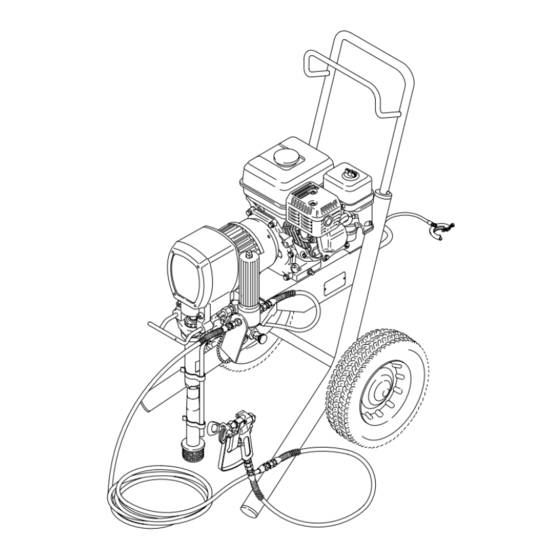
GM 5000 Convertible
Airless Paint Sprayer
3000 psi (210 bar) Maximum Working Pressure
Model 231-316, Series A
Basic sprayer, without hose or gun
Model 231-331
Complete sprayer, with hose and Contractor gun,
RAC IV
DripLess
Tip Guard,
and 517 size SwitchTip
Optional Electric Motor Kit
Model 236–379
This 2 HP electric motor accessory converts
the unit to an electric powered sprayer in
just seconds.
Model 236–784
Same as Optional Kit 236–379 except
this Kit is CSA certified.
GRACO INC. P.O. BOX 1441 MINNEAPOLIS, MN 55440-1441
This manual contains important
warnings and information.
READ AND RETAIN FOR REFERENCE
COPYRIGHT 1993, GRACO INC.
308-327
Rev. B
Supersedes A
02686
Advertisement
Table of Contents

Related Manuals for Graco GM 5000


Summary of Contents for Graco GM 5000
- Page 1 This 2 HP electric motor accessory converts the unit to an electric powered sprayer in just seconds. Model 236–784 Same as Optional Kit 236–379 except this Kit is CSA certified. 02686 GRACO INC. P.O. BOX 1441 MINNEAPOLIS, MN 55440-1441 COPYRIGHT 1993, GRACO INC.
-
Page 2: Table Of Contents
The drawing shows the best placement Spanish 185–961 of these labels for good visibility. German 186–041 Greek 186–045 Korean 186–049 Order the labels directly from Graco, free of charge. English 185–593 Toll Free: 1–800–328–0211 0162 FIRE AND SKIN INJECTION... - Page 3 NOTES...
- Page 4 WARNINGS High Pressure Spray Can Cause Serious Injury. For Professional Use Only. Observe All Warnings. Read and understand all instruction manuals before operating equipment. FLUID INJECTION HAZARD General Safety Safety Latch This equipment generates very high fluid pressure. Spray from Whenever you stop spraying, even for a moment, always set the gun, leaks or ruptured components can inject fluid through the gun safety latch in the closed or “safe”...
- Page 5 DO NOT expose Graco hoses to temperatures above 180 F (82 All fluid hoses must have strain reliefs on both ends! The strain C) or below -40 F (-40 C).
- Page 6 AVERTISSEMENT La pulvérisation à haute pression peut causer des blessures très graves. Réservé exclusivement à l’usage professionnel. Observer toutes les consignes de sécurité. Bien lire et bien comprendre tous les manuels d’instructions avant d’utiliser le matériel. RISQUES D’INJECTION Consignes générales de sécurité Verrou de sécurité...
- Page 7 RISQUES EN CAS DE MAUVAISE UTILISATION DU MATERIAL Consignes générales de sécurité Pression Toute utilisation anormale de l’appareil du pulvérisation ou des ac- Ce pulvérisateur peut produire une Pression Maximum De T ravail 210 bar (3000 lb/po. ). S’assurer que tous les éléments du pulvéri- cessoires comme, par exemple, la mise sous une pression excessi- ve, les modifications de pièces, l’utilisation de produits chimiques et sateur et ses accessoires sont conçus pour résister à...
- Page 8 ADVERTENCIA EL ROCIADO a ALTA PRESIÓN PUEDE CAUSAR GRAVES LESIONES. SOLO PARA USO PROFESIONAL. RESPETE LOS AVISOS DE ADVERTENCIA. Lea y entienda todo el manual de instrucciónes antes de manejar el equipo. PELIGRO DE INYECCION DE FLUIDO Seguridad general Aparatos de seguridad de la pistola pulverizadora Este equipo general un fluido a una presión muy alta.
- Page 9 PELIGRO POR MAL USO DEL EQUIPO Seguridad general Presión del sistema Cualquier mal uso del equipo pulverizador o los accesorios, tal Esta pulverizadora puede desarrollar 210 barías (3000 psi) de Presion De T rabajo Maxima. Asegurar que todo el equipo pul- como sobre presurización, modificación de piezas, uso de ma- teriales y productos químicos incompatibles, o utilización de verizador y sus accesorios tienen la capacidad para aguantar...
-
Page 10: Warnings
Setup WARNING 4. Fill the packing nut/wetcup (416). One full squirt of Graco Throat Seal Liquid (TSL) is usually If you are supplying your own hoses and spray enough. gun, be sure the hoses are electrically conductive, that the gun has a tip guard, and that each part is rated for at least 3000 psi (210 bar) Maximum Working Pressure . -
Page 11: Fueling
Setup 5. Check the engine oil level. Refer to the Honda engine manual, supplied. This is a summary of the information: Remove one of the oil fill plugs (C); the oil should be almost overflowing. See Fig 2. Add oil as necessary. Recommended lubrication oil: Use a high-quality, detergent oil, SAE 10W-40, classified “FOR SER- VICE SE or SF”, for regular use and for breaking-... -
Page 12: Startup
Startup 11. Turn OFF the pressure control switch (B). CAUTION Never try to start the engine unless fluid pressure Trigger safety is relieved and the pressure control switch is OFF. latch shown Trying to start the engine when it is pressurized engaged could damage the recoil system. - Page 13 Startup 4. Close the pressure drain valve (60). See Fig. 4. 6. Install the spray tip (C) in the gun. See the sepa- Squeeze the trigger until fluid flows from the gun. rate tip instruction manual, 307-848, supplied. This primes the hoses. Release the trigger. En- gage the gun safety latch.
-
Page 14: Maintenance
Maintenance CAUTION Daily: Check the engine oil level and fill as necessary. See Step 5, page 11. Close the black fuel shutoff lever (G) when trans- porting the sprayer to prevent fuel from flooding the Daily: Check and fill the gas tank. See page 11. engine. - Page 15 Flushing How to Flush 7. Check all fluid connections for leaks. Relieve pres- sure before tightening any connections. Start the NOTE: “Solvent” refers to water or oil-based solvent. sprayer. Recheck the connections for leaks. 1. Follow the Pressure Relief Procedure on page 8.
-
Page 16: Troubleshooting
Connect cable on top of engine or replace spark spark plug damaged plug. Water frozen in pressure control Return pressure control to authorized Graco dealer for repair. Engine won’t “pull over” Oil seepage into combustion Remove spark plug. Pull starter rope 3 or 4 times. - Page 17 PROBLEM CAUSE SOLUTION Displacement pump Pump inlet screen clogged Clean. output low on upstroke output low on upstroke Piston ball check not seating Service piston ball check. See page 31. Piston packings worn or damaged Replace packings. See page 31. Sleeve gasket in displacement pump is Replace.
-
Page 18: Bearing Housing And Connecting Rod
Bearing Housing and Connecting Rod WARNING CAUTION To reduce the risk of serious injury, always follow DO NOT use the bearing housing screw (73) to the Pressure Relief Procedure Warning on page align or seat the bearing housing with the drive 16 before repairing the sprayer. -
Page 19: Drive Housing
Drive Housing WARNING CAUTION To reduce the risk of serious injury, always follow Do not drop the gear cluster (16) when removing the Pressure Relief Procedure Warning on page the drive housing (5). The gear cluster is easily 16 before repairing the sprayer. damaged. -
Page 20: Pinion
Pinion Remove the Pinion Housing Repairing the Pinion WARNING NOTE: Repair Kit No. 236–394 includes the shaft and bearings pre-assembled and lubricated. A hydraulic To reduce the risk of serious injury, always follow press is not required. Use the repair procedure below. the Pressure Relief Procedure Warning on page 16 before repairing the sprayer. -
Page 21: Clutch
Clutch NOTE: The clutch assembly (212) includes the arma- 4. Tap lightly on the back of the bearing housing (11) ture (212a) and rotor (212b). The armature and rotor with a plastic mallet to loosen the drive housing must be replaced together so they wear evenly. assembly (5) from the clutch housing (222). -
Page 22: Field And Wiring Harness
Field and Wiring Harness NOTE: Refer to Fig. 11. 1. Pull the plastic caps (A) off the wire screws (22) in both places on the field. Loosen the screws and release the wires (64). 2. Loosen the four setscrews (211). Pull off the field (210). - Page 23 Alternator D, 203 See Fig. 12 for a detail of CUTAWAY VIEW where 206 connects Fig. 15 02728 NOTE: Refer to Fig. 15 which also shows the the mounting bracket. When pressing the shaft assembly in a cutaway view. (209) through the bearing (204), press it until the groove D is exposed, then install the retaining ring 4.
-
Page 24: Reassembly
Reassembly 1. Install the field (210) in the clutch housing (222). 3. Be sure the face of the armature (212b) is clean. Working through the slot in the clutch housing, Assemble the armature to the hub in the pinion connect the wires of the harness (64) to the housing (219). - Page 25 NOTES...
-
Page 26: Pressure Control Replacement
Pressure Control Replacement WARNING 3. Working under the cart, disconnect the wires (A). See Fig. 20. To reduce the risk of serious injury, always follow the Pressure Relief Procedure Warning on page 16 before repairing the sprayer. Note the original location of these hoses. - Page 27 Pressure Control Replacement 6. Disconnect the black, red and white wires from the 9. Use a wrench to hold the hex of the adapters (A) rectifier (307) and switch (302), which are while removing the elbows (318). sheathed with the conductor (316). See Fig. 22. 7.
-
Page 28: Pressure Control Adjustment
Pressure Control Adjustment WARNING USE EXTREME CAUTION WHEN PERFORMING NEVER attempt to increase the fluid outlet pressure THIS CALIBRATION PROCEDURE to reduce the by performing these calibrations in any other way. risk of a fluid injection injury or other serious bodily NEVER EXCEED 3000 psi (210 bar) MAXIMUM injury, which can result from component rupture, WORKING PRESSURE. - Page 29 Pressure Control Adjustment Set the Dead Band (Pressure Differential) Adjust the Pressure NOTE: Do not alter this adjustment if the wheel is al- 1. Remove the plug (326) in the bottom of the pres- ready set as shown in Fig. 24. sure control.
-
Page 30: Pump
NOTE: The pump repacking procedure begins on page bodily injury. If the sleeve cannot be removed easi- ly using the tool, return the sleeve and cylinder to your Graco distributor for removal. - Page 31 Pump Pump Repacking WARNING To reduce the risk of serious injury, always follow the Pressure Relief Procedure Warning on page 16 before repairing the sprayer. 1. Flush the pump, if possible. Relieve pressure, stopping the pump with the piston rod in its lowest position, if possible.
- Page 32 Pump Fig. 32 02559 Fig. 36 02563 8. Disassemble intake valve. Use a pick to remove 12. Loosen the retaining nut. Unscrew the piston valve the old gasket. Clean and inspect. from the rod. Clean and inspect the parts. 421* *404 *402 02560...
- Page 33 Pump *410 415* *412 406* 403* *414 Fig. 39 02566 Fig. 42 02569 15. Clean the piston valve threads. One at a time, stack the backup washer (403*), seal (415*) (with 18. While maintaining the alignment, thread the piston lips facing down), and female gland (414*) on the valve assembly into the piston rod just until the piston.
- Page 34 Pump Fig. 45 02572 21. Loosely install the packing nut and plug. Fig. 49 02576 25. Slide the sleeve/piston rod assembly into the bottom of the cylinder. 417* Fig. 46 02573 22. Place a new o-ring (417*) in the cylinder. Slide the sleeve in to the cylinder up side down to seat the o-ring.
- Page 35 02581 Tighten the packing nut just enough to stop leak- 30. Push the retaining spring into the groove all the age, but no tighter. Put one full squirt of Graco way around the connecting rod. TSL in the packing nut.
- Page 36 Parts – Basic Sprayer See alternate view of 74 above See alternate view of 74 below See exploded view on page 38 Ref 74 See parts on page 40 See engine detail on page 37 Part of cart See parts on page 41 Ref 219d Ref 63 Ref 63...
-
Page 37: Clutch Housing Alternator
Parts – Basic Sprayer Model 231–316, Series A Ref. Part No. Description Qty. Ref. 220–285 Part No. Description Qty. 178–034 TAG, warning 802–264 ENGINE, 5 HP 222–198 PRESSURE DRAIN VALVE 236–397 CLUTCH HOUSING ALTERNATOR 100–840 ELBOW, street, 1/4–18 npt (m x f) See separate parts list on page 38 235–542 FLUID HOSE, 3/8”... - Page 38 Parts – Clutch Housing Alternator 219a 219e 218f 219b 218d 219c 218a 219d 218e 218c 218b 02697 212a 212b 02737 Lubricate exterior Lubricate inner and outer diameters Lubricate teeth Press fit before 218f Press fit after 218d Ref No. 2 Part No.
- Page 39 Parts – Complete Sprayer Model 231–331 Includes items 125 to 128 Ref. Part No. Description Qty. 231–316 CONVERTIBLE GM5000 Basic Sprayer See parts list on page 37 223–541 HOSE, grounded, nylon; 1/4” ID; cpld 1/4 npsm(fbe); 50 ft (15 m);’ spring guards both ends 214–701 HOSE, grounded, nylon;...
- Page 40 Parts – Pump Model 220–872, Series A Carbon Steel Displacement Pump Includes items 2 to 25 Part No. Description PTFE 402* 107–098 PACKING, o–ring, 403* 108–690 SEAL, u–cup, polyurethane 404* 108–775 BALL; sst 183–171 PLUG 1 409* 406* 183–174 V–PACKING, leather 425* 407* 183–175...
- Page 41 Parts – Pressure Control Part No. 222–369 – Basic Pressure Control for the GM5000 Sprayers Includes items 300 to 315 only. Order the Basic Pressure Control 222–369, and items 314 to 319 as required. Ref. Ref. Part No. Description Qty. Part No.
-
Page 42: Wiring Schematic
Wiring Schematic – Pressure Control Alternator Main switch Rectifier Clutch Field Adjustable pressure switch 0054... - Page 43 Manual Change Summary This manual was revised to add a CSA certified The following parts were also changed: optional electric motor kit, 236–784, to the manual. In Assembly Part Ref. Part No. Name addition, the arrow shown in Fig. 31, page 31, was cor- Changed Status rected to show it turning in the correct direction;...
-
Page 44: Technical Data
Graco distributor to the original purchaser for use. As purchaser’s sole remedy for breach of this warranty, Graco will, for a period of twelve months from the date of sale, repair or replace any part of the equipment proven defec- tive, with the exception of defects in parts on the drive train/gear box on EM and GM sprayers or power train on EH and GH sprayers, which will be repaired or replaced for twenty-four months from the date of sale for Gas–Hydraulic (GH) and Gas-Me-...
Need help?
Do you have a question about the GM 5000 and is the answer not in the manual?
Questions and answers