
Summary of Contents for Re Revision II Plus Touch
- Page 1 ReVision II plus Touch Viewing system INSTALLATION, USE AND MAINTENANCE MANUAL Original instructions CAUTION ! THE POWER SUPPLY MUST BE DISCONNECTED BEFORE UNPLUGGING THE CABLES...
-
Page 3: Table Of Contents
Warnings ......................... 1 Handling instructions ..................... 1 Safety notes ........................1 Assembling the ReVision II plus Touch on the end machine ........3 Mechanical dimensions........................8 Electrical cables and synchronisation sensors connection ........12 Connection to the network or to PC ....................18 About ReVision II plus Touch .................. -
Page 4: Warnings
When handling take care not to knock the ReVision II plus Touch as this may damage it. Safety notes The ReVision II plus Touch viewing system must be fitted and used by qualified technical personnel, in compliance with the safety norms required for the environment the machine is installed in. - Page 5 S.p.A. ReVision II plus Touch Warning: ReVision II plus Touch has not a start/stop button, so, in order to switch on or off the viewing system, you must switch on or off the machine to which it has been applied.
-
Page 6: Assembling The Revision Ii Plus Touch On The End Machine
S.p.A. ReVision II plus Touch Assembling the ReVision II plus Touch on the end machine To assemble the viewing system wear safety gloves and boots and observe all the safety norms required for the environment in which it is installed. - Page 7 S.p.A. ReVision II plus Touch Follow the steps indicated below only if the system cannot be supplied with the rail assembled on the camera (for manual models, follow the steps described below, however, as the units are not fitted with a toothed...
- Page 8 S.p.A. ReVision II plus Touch 3. Connect the signal+power supply cable to the camera and to the motorized rail a. Take off the top of the cable conduit placed at the rear of the motorized rail and insert the signal+power supply and the earthing cables in the conduit.
- Page 9 S.p.A. ReVision II plus Touch 4. Adjust the eccentrics if there is play between the camera and the rail: rotate the eccentrics with a 17 spanner (drawing 1) and tighten them with an Allen wrench (drawing 2). Warning! The small wheels must not remain blocked but must be able to rotate freely.
- Page 10 S.p.A. ReVision II plus Touch d. Remove the screw from the belt tightening block and insert the belt. Belt inserted in the Screw M6 belt tightening block Remove this to allow putting the belt in the belt tightening block e. Scroll the belt tightening block so that the belt is tightened, then place again the screw and tighten it.
-
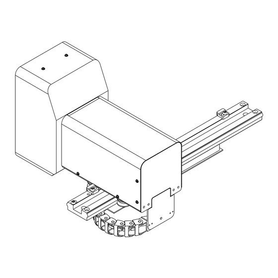
Page 11: Mechanical Dimensions
S.p.A. ReVision II plus Touch Mechanical dimensions ReVision Camera Touch 75 Rev.21/05/13 8/51... - Page 12 S.p.A. ReVision II plus Touch ReVision Camera Touch 100 Rev.21/05/13 9/51...
- Page 13 S.p.A. ReVision II plus Touch ReVision Camera Touch 350 Rev.21/05/13 10/51...
- Page 14 S.p.A. ReVision II plus Touch ReVision DSP plus Touch Rev.21/05/13 11/51...
-
Page 15: Electrical Cables And Synchronisation Sensors Connection
1024x768 LCD ReVision II plus Touch has not a start/stop button. Connect the power supply cables of the viewing system to the machine to which it has been applied so that you can switch on and off the viewing system by switching on and off the machine. - Page 16 S.p.A. ReVision II plus Touch Applications for synchronization signals: Version Sensors Connection of connector With 1 sensor 1 PROXIMITY “sensor 1” connector 1 ENCODER “sensor 1” connector 1 EXTERNAL “sensor 1” connector SYNCHRONIZATION Pin 9 = 10÷30Vdc SIGNAL Pin 8 = 0V...
- Page 17 Below are the indications relative to sensors that can be used to detect the synchronisation signals which can be supplied by Re S.p.A. If you have other sensor available, or if in doubt, contact the Re technical assistance team or your local agent.
- Page 18 S.p.A. ReVision II plus Touch Contrast sensor Teach-in button Sender light (red or green or blue) and status indicator Fit it perpendicularly to the sheet so that it reads the notches at start/end print. In the case of objects with reflective or shiny surface, tilt sensor by 10°...
- Page 19 S.p.A. ReVision II plus Touch Encoder Connect it to the print cylinder with the shaft or to stamp roller gears. If the Encoder is with single channel (to read the teeth number) or with double channel (to read the teeth number and the start of print), it must be connected to the “sensor 1” connector.
- Page 20 S.p.A. ReVision II plus Touch Other synchronisation sensor or external signal (supplied by customer) If you use a synchronisation sensor to read the teeth number, different from the sensors described above, connect it to the “sensor 1” connector and implement the following electrical...
-
Page 21: Connection To The Network Or To Pc
S.p.A. ReVision II plus Touch Connection to the network or to PC (only for LD and CV system) If settings for Ethernet connection has been required (available only for LD and CV viewing system), carry out the connection to the company network or to PC (point-to-point configuration). This enables the company network or another PC to access the file containing the images memorized by the viewing system. -
Page 22: About Revision Ii Plus Touch
ReVision II plus Touch About ReVision II plus Touch ReVision II plus Touch is a viewing system which allows the operator to see, check and improve print quality. The touch screen interface offers a number of advantages over the classic keyboard. Not only is it simple to use and intuitive, it also provides rapid access to all the functions and does not have any cables or wires that can get in the way or be damaged. -
Page 23: Quick Start
1. Assemble the viewing system on the end machine and connect all system components following the instructions in the previous sections (from page 3 to page 18). 2. Switch on the machine to which the ReVision II plus Touch system has been applied: the viewing system will switch on automatically. - Page 24 S.p.A. ReVision II plus Touch 5. In order to access the set-up icons, touch the screen twice in rapid succession, the following page is displayed. 6. Set the number of print cylinder teeth, the number of revolutions per flash, the number of sensors installed and, for motorized cameras, the software limit switches through the Rail setup function (details in Detailed description of functions on page 36).
-
Page 25: Device Functioning
S.p.A. ReVision II plus Touch Device functioning The user can access the most common system functions (e.g. zoom adjustment, autoscan, etc.) directly from the working page. Touch any point on the screen to display the corresponding icons (if no icons are selected within a few seconds they disappear, touch any point on the screen in order to display them again). -
Page 26: Set-Up Page Commands
S.p.A. ReVision II plus Touch Set-up page commands When on the working page, touch any point on the screen twice in rapid succession to access the set-up page (see screen shot on the left) where the operator can carry out all the system settings, and where the various function icons are displayed. - Page 27 S.p.A. ReVision II plus Touch CAMERA SELECTION Function not active (the icon appears grey-coloured on the screen) AUTOSCAN TYPE Press this button to select the type of autoscan that is activated by pressing the autoscan button. (details on page 26).
- Page 28 S.p.A. ReVision II plus Touch SENSORS NUMBER Press this button to set the number of sensors connected to the system (details on page 39). LAMPS Press this button to select which flash lamp to activate or whether to use them both (details on page 39).
-
Page 29: Camera And Rail Functioning
S.p.A. ReVision II plus Touch Camera and rail functioning The mode button allows to change the camera state: a brief pressure of the button changes the camera state from Run to Stop and vice versa; keeping pressed the button for about 5 seconds, the camera goes in Test mode. - Page 30 S.p.A. ReVision II plus Touch Vertically, along the same line Continuously horizontally Programmed scan The horizontal autoscan and continuous horizontal autoscan use the horizontal movement of the camera: during these functions the camera moves on the rail in both of directions. To carry out this movement, the system must know the points, called software limit switches, in which to invert direction.
-
Page 31: Memorization, Loading And Comparison Of Images
S.p.A. ReVision II plus Touch Memorization, loading and comparison of images The camera is able to memorize one or more images (according to the viewing system version) and to maintain it displayed on the screen contemporaneously as the image that is acquired each time. These functions can be easily and immediately managed with the save (image memorization), goto (image loading) and split (splitting the screen) buttons. - Page 32 S.p.A. ReVision II plus Touch MH, LD and CV VERSIONS: With these versions of the viewing system you can save up to 8 images to use for comparing with the images taken each time by the laminate. LD and CV systems can store up to 10 different working program images and call them up rapidly when it is necessary to compare them, execute a programmed scan, or reconstruct an image, depending on the type of process to be carried out.
- Page 33 S.p.A. ReVision II plus Touch Loading of images: (to select which image to use for the comparison with the current sheet image) pressing the load button in the Run mode (when there is an acquired frame on the screen), ...
- Page 34 S.p.A. ReVision II plus Touch To view the comparison on the working page, touch any point on the screen twice in rapid succession: the image appears in full screen mode. All the saved images and the last image loaded stay in the memory even when the system is switched OFF.
-
Page 35: Programmed Scan
S.p.A. ReVision II plus Touch Programmed scan Programmed scan function (available only for LD and CV versions), this allows the viewing system to take a determined sequence of images from the sheet prior to its being saved. Below we describe the process for carrying out the programmed scan. - Page 36 S.p.A. ReVision II plus Touch Warning! During programmed scan the autoscan button is the only one active (this one allows to stop the autoscan function). If you press any other icon the following message appears. Press OK if you want to cancel the function or Cancel if you want to continue with programmed scan.
-
Page 37: Image Reconstruction
S.p.A. ReVision II plus Touch Image reconstruction The image reconstruction (available only for LD and CV versions) is useful for very large sheets as it allows the entire print image to be obtained and to select the exact point from which you desire to acquire the image. - Page 38 S.p.A. ReVision II plus Touch Warning! During image reconstruction no icons are active. If any icon is pressed the following message appears on the screen. Press OK if you want to cancel the function or Cancel if you want to continue with programmed scan.
-
Page 39: Detailed Description Of Setting Functions
S.p.A. ReVision II plus Touch Detailed description of setting functions Functions Possible options Default settings AUTOSCAN TYPE Horizontally Vertically Vertically Continuously horizontally Programmed scan COLOUR SPOT DIMENSION 4x4 - 8x8 - 16x16 16x16 CONTROL COLOUR TYPE only for RGB-N LD and CV... - Page 40 S.p.A. ReVision II plus Touch AUTOSCAN TYPE This function enables the operator to select the type of autoscan to be executed (the autoscan is executed by pressing the autoscan button). Press the lock/unlock button to unlock the protected commands, then press the autoscan type button to select the desired option.
- Page 41 S.p.A. ReVision II plus Touch COLOUR TYPE To select the colours type you desire the system read during the Colour control function RGB = the quantity of red, green and blue colours are shown on the screen rgb = the normalized quantity of red, green and blue colours are shown on the screen...
- Page 42 S.p.A. ReVision II plus Touch or Test state and the autoscan in Stop. Then, press the lock/unlock button to unlock the protected commands, press the rail setup image, and press the left or right arrow until the camera reaches one...
- Page 43 S.p.A. ReVision II plus Touch INVERT VERTICAL ARROWS To invert the functions of the vertical arrows to facilitate camera control. Press the lock/unlock button to unlock the protected commands. Each time the operator presses the invert vertical arrows button the functions of the two vertical arrow functions are inverted.
-
Page 44: Teeth Number
If the value set is incorrect, the acquisition will not be synchronised with the print. If you use the Encoder provided by Re S.p.A. and it is mounted so that the Encoder and the print cylinder are coaxial, set 100; instead if the Encoder is not mounted on the same axis of the print cylinder, the value you have to set depends on the possible transmission ratio between the Encoder turns and the print development. -
Page 45: Troubleshooting
S.p.A. ReVision II plus Touch Troubleshooting Problem Possible causes Remedies System does not start No DSP Touch power Connect the DSP Touch to the 24V dc power supply System starts but monitor does The VGA connecting cable or the Check that both cables are... - Page 46 S.p.A. ReVision II plus Touch Warning! If needing to contact our technical support service, you must communicate the model and serial number of your camera and DSP Touch. This information is found on the special plates on the Bussero (MI) ITALY camera and on the rear part of the DSP, as shown in the following diagrams.
-
Page 47: Technical Specifications
S.p.A. ReVision II plus Touch Technical specifications Suitable for labelling machines. Optical zoom Digital zoom Field of view 75 x 90 mm Movement manual or motorized Images memorization 1 image MH-75 Optical zoom Digital zoom Field of view... - Page 48 S.p.A. ReVision II plus Touch Working voltage of external power supply 90÷264Vac/100÷300Vdc with Cabur power supply unit unit, with 10m cable mod. XCSF (automatic selection) Power supply of DSP Touch 24Vdc / 5A by external power supply unit ...
-
Page 49: Maintenance
Maintenance Caution! Before performing any operation on the viewing system ReVision II plus Touch whatsoever, switch off the machine to which it has been applied so that also the viewing system is off. Caution: due to the presence of capacitors in the video camera and DSP Touch, high voltages may be present even when the system is switched off. -
Page 50: Replacing The Lamps
S.p.A. ReVision II plus Touch Replacing the lamps Caution! We recommend to replace the lamps only if the machine (and consequently the viewing system) is switched off for at least one minute and when the material is NOT running! In the ReVision camera Touch model 75 there is one single lamp, whilst in models 100 and 350 there are two;... -
Page 51: Replacing The Filter Sponges
S.p.A. ReVision II plus Touch Replacing the filter sponges Caution! We recommend to replace the filter sponges of the DSP only if the machine (and consequently the viewing system) is switched off for at least one minute and when the material is NOT running! The filter sponges are in the two boxes on the DSP. -
Page 52: Cleaning The Uv Filter
S.p.A. ReVision II plus Touch Cleaning the UV filter Caution! We recommend to clean the UV filter only if the machine (and consequently the viewing system) is switched off for at least one minute and when the material is NOT running! When necessary clean the UV filter positioned inside the camera, in front of the zoom box. -
Page 53: Disassembly And Dismantling
To disassemble the ReVision II plus Touch from the machine simply remove the 2 screws used to fix the motorized rail to the machine (see figure on page 3) -
Page 54: Guarantee
ReVision II plus Touch Guarantee Re S.p.A. guarantees this device against all defects relative to the materials and manufacturing for a period of 12 months from the date of delivery. Should your device develop operating faults during the guarantee period, please contact the Company’s agent in your country, or, if this is not possible, contact Re S.p.A. - Page 56 Re S.p.A. Controlli Industriali Via Firenze, 3 - 20060 BUSSERO (MI) ITALY Fax (+39) 02 95 03 89 86 Technical support: Tel. (+39) 02 95 24 30.300 - E-mail: support@re-spa.com Sales support: Tel. (+39) 02 95 24 30.200 - E-mail: sales@re-spa.com www.re-spa.com...
Need help?
Do you have a question about the Revision II Plus Touch and is the answer not in the manual?
Questions and answers