Table of Contents
Advertisement
Quick Links
Advertisement
Table of Contents

Related Manuals for AeroVonics AV-20

Summary of Contents for AeroVonics AV-20
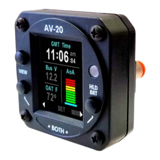
- Page 1 D-0011-0, AV-20 Installation Manual AV-20 / AV-20-S Multi-Function Display Part Number U-1001-0 / U-1002-0 Installation Manual (D-0011-0, AV-20, INSTALLATION MANUAL, REV B) AeroVonics LLC Albuquerque, New Mexico 10/03/2018 Page 1 of 13 Revision B...
-
Page 2: Table Of Contents
D-0011-0, AV-20 Installation Manual Document Revisions Revision Date Description of Change Author PDF Sig 09/20/2017 Initial Release 10/03/2018 Updated for initial NORSEE certification, latest UI for Software Release 1.0. Updates from FAA Review. Table of Contents 1 System Description ...................... 3 2 Model Variants &... -
Page 3: System Description
D-0011-0, AV-20 Installation Manual 1 System Description The AeroVonics AV-20 and AV-20-S Multi-Function Displays provide a wide array of supplemental flight information. Features Include: • AoA Display (Voice Alerting & Peaks) • G-Meter Display (Voice Alerting & Peaks) • Attitude (Roll / Pitch) •... -
Page 4: Model Variants & Required Interfaces
D-0011-0, AV-20 Installation Manual 2 Model Variants & Required Interfaces The AV-20 is available in two configurations: • AV-20 (Part Number U-1001-0): The base model does not include internal inertial sensors or pitot-static sensors. Functions are limited to those indicated below. •... -
Page 5: Equipment Connections
This is provided for upgrade purposes and are plugged from the factory. Do not remove the plugs. Do not connect Pitot and Static in the AV-20 Base model units. Pitot and Static connections ARE required in the AV-20-S Model for proper functionality. -
Page 6: Manufacturing Port
Class I and II aircraft. Installation in pressurized aircraft, or other categories of aircraft may require additional certification activities. The AV-20 model is limited to installation in Part 23, Class I and II aircraft. Installation in other categories of aircraft may require additional certification activities. -
Page 7: Operating Limits
D-0011-0, AV-20 Installation Manual 4 Operating Limits The following operational limitations are applicable: Operating Limits Angle of Attack Range 0° to +30° Angle of Attack Resolution 1° Angle of Attack Operation +35 to +300 Knots Angle of Attack Accuracy 2.5°... -
Page 8: System Specifications
Viewing Angle Up 45° Viewing Angle Down 10° Backlight Lifetime (Typical) 50,000 Hrs Table 3 - System Specifications 6 Intended Function Reference the Pilots Guide (D-0014-0, AV-20, Pilots Guide; Intended Function Section) for intended functionality. 10/03/2018 Page 8 of 13 Revision B... -
Page 9: Installation
D-0011-0, AV-20 Installation Manual 7 Installation 7.1 Overview Installation consists of the following steps: • Remove / relocate any old instrumentation • Add or locate an appropriate power source / breaker • Wire power and interfaces as needed • Mount the unit to the instrument panel with supplied screws •... -
Page 10: Wiring Diagram
D-0011-0, AV-20 Installation Manual 7.3 Wiring Diagram **ROTATING THE PLASTIC TUBE WHILE REMOVING WILL IMPORTANT! CONNECT PITOT AND STATIC QUICK CONNECT: IN AV-20-S MODEL ONLY MINIMIZE RISK OF DAMAGING THE QUICK-CONNECT FITTING ** PUSH RELEASE RING IN TOWARD UNIT TO RELEASE... -
Page 11: Setup
To Aircraft Ground Table 4 – Connector Pinout 7.4 Setup Refer to D-0014-0, AV-20, Pilots Guide for detailed setup options and procedures. All options are available to the pilot to configure as desired. A summary of the options are as follows:... -
Page 12: Instructions For Continued Maintenance & Operation
The AV-20 system may be used for supplemental information but may not replace any equipment required under 14 CFR 91.205. • The AV-20 system is not a required system and may not be used as a substitution for the certificated aircraft system. •... - Page 13 D-0011-0, AV-20 Installation Manual o During power on, the ALIGNING mode on the Attitude Indicator page remains for more than 2 minutes. Note the Hard Calibration must be performed while not in flight, and with as little aircraft motion present. Preferred location is inside a hanger with doors closed.
Need help?
Do you have a question about the AV-20 and is the answer not in the manual?
Questions and answers