
Summary of Contents for SolarShine SR981
- Page 1 SR971,SR972 Solar station operation manual -------------------------------------------------------------------------------------------------------------------------------------...
-
Page 2: Table Of Contents
1.3 Important remark---------------------------------------------------------------------------------------4 1.4 Description of symbols-------------------------------------------------------------------------------5 2. Overview of solar station------------------------------------------------------------------------------5 2.21 Technical date of solar station SR981 & SR982 -------------------------------------------8 3. Mounting of solar station-----------------------------------------------------------------------------10 4. Attention Items for solar station installation ---------------------------------------------------10 5. Wire connection of solar controller---------------------------------------------------------------12 5.1 Open the connection box--------------------------------------------------------------------------12... - Page 3 SR971,SR972 Solar station operation manual function)---------------------------------------------------------------------------------------------------33 7.6.3 Submenu - CMN Low temperature protection of collector---------------------------34 7.6.4 Submenu - CFR Frost protection of collector-------------------------------------------35 7.6.5 Submenu - REC Tank recooling temperature-------------------------------------------36 7.6.6 Submenu – SMX1 Maximum temperature of tank------------------------------------36 7.6.7 Submenu - C-F Celsius and Fahrenheit temperature transferring---------------37 7.7 Main menu - FUN Auxiliary function----------------------------------------------------------37 7.7.1 Submenu - DVWG Anti-Legionella function----------------------------------------------38 7.7.2 Submenu - CIRC...
- Page 4 SR971,SR972 Solar station operation manual 9.1 Trouble protection-----------------------------------------------------------------------------------52 9.2 Trouble checking------------------------------------------------------------------------------------53 10 Quality Guarantee------------------------------------------------------------------------------------55 11. Technical data----------------------------------------------------------------------------------------56 12. Delivery scope---------------------------------------------------------------------------------------57 13. Devices matchable to this controller-----------------------------------------------------------57 -------------------------------------------------------------------------------------------------------------------------------------...
-
Page 5: Safety Information
SR971,SR972 Solar station operation manual 1.Safety information 1.1 About this manual This manual describes the installation, function and operation of a solar station, which integrates a solar controller. When installing the remaining components e.g. the solar collectors, pump assemblies and the storage unit, be sure to observe the appropriate installation instructions provided by each manufacturer. -
Page 6: Description Of Symbols
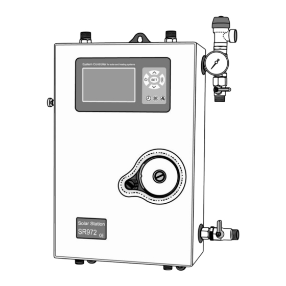
SR971,SR972 Solar station operation manual 1.4 Description of symbols Safety symbol: Safety instructions in the text are marked with a warning triangle. They indicate measures which can lead to injury of persons or safety risks. Operation steps: small triangle “►”is used to indicate operation step. Notes: Contains important information on operation or function. - Page 7 SR971,SR972 Solar station operation manual 2.18 2.19 2.20 2.17 2.16 2.10 2.11 2.12 2.15 2.13 2.14 SR972 double pipeline system SR971: Solar station with one pipe, SR972: solar station with double pipes , This picture is according to SR972 2.1 Connection from collector ,male thread G1/2, (not exist on SR971) 2.2 Upper mounting hole 2.3 Connection to collector, male thread G1/2 2.4 Safety valve, 6bar...
- Page 8 SR971,SR972 Solar station operation manual 2.12 Connection box of controller 2.13 Bottom mounting hole 2.14 Connection from tank, male thread G1/2 2.15 Connection to tank, male thread G1/2 ( not exist on SR971) 2.16 Air saperator including manual release valve (not exist on SR971) 2.17 Return pipe temperature sensor, NTC10K, B=3950(not exist on SR971) 2.18 Front insulation cover 2.19 Operation panel of controller...
-
Page 9: Technical Date Of Solar Station Sr981 & Sr982
SR971,SR972 Solar station operation manual 2.21 Technical date of solar station SR971 & SR972 Parts description of solar Parameter Remark station Solar station Height 420mm Width 280mm Thickness 140mm Distance between flow/return 160mm Max. permitted pressure 10 bar Max. permitted temperature 130℃... - Page 10 SR971,SR972 Solar station operation manual Gravity brake Output 0~16bar Version Max. permitted temperature -20~120℃ Flowmeter Display/setting range 0.1~20L/min Air seperator ( no in SR971) Connections flushing/filling unit For hose fitting G1/2 Thermal insulation Material for back and front EPS/EPP 2 kinds of material can be casing chose Material for front cover...
-
Page 11: Mounting Of Solar Station
SR971,SR972 Solar station operation manual of solar station Mounting ► Drill the upper fixing hole ► Fasten the screw ► Mark the bottom fixing hole ► Drill the bottom hole ► Fasten the bottom screw 4. Attention Items for solar station installation -------------------------------------------------------------------------------------------------------------------------------------... - Page 12 SR971,SR972 Solar station operation manual Note: In order to avoid jaming the degital flow meter and in result to displays no flow on solar station, the filter ( A) must be installed on the return and flow pipeline of solar station.
-
Page 13: Wire Connection Of Solar Controller
SR971,SR972 Solar station operation manual 5. Wire connection of solar controller 5.1 Open the connection box ►Loosen the fixing screw (B) which is on the back of connection box ►Pull out the connection box downwards parallelly. ( C) ►Loosen the protection screw ( D), open the cover of terminal upwards ►... -
Page 14: Change Fuses
SR971,SR972 Solar station operation manual Note: Please use delivered clamps to fix wires correctly. ( F) 5.2 Change fuses ► Use screw driver(see as picture) , turn to left to spring fuse, fuse parameter: AC250V/6.3A 5.3 Terminal connection Layput of terminals -------------------------------------------------------------------------------------------------------------------------------------... - Page 15 SR971,SR972 Solar station operation manual Power connection Input is for power connection, is for connection with ground . Input ports Input T1: PT1000 temperature sensor use for collector. Input T2 ~T5: NTC10K, B=3950 temperature sensor, for measuring temperature of tank and pipeline ...
-
Page 16: Control Operation Description
SR971,SR972 Solar station operation manual Output ports Output R2:electromagnetic relay, max. switching current 3.5A, R2 ports wire connection:for tank thermostat function Output R3:electromagnetic relay, max. switching current 3.5A, R3 ports wire connection:for tank cooling function. Output R4:electromagnetic relay, max. switching current 3.5A, R4 ports wire connection:for hot water circuit pump function. -
Page 17: Signal Description
SR971,SR972 Solar station operation manual Note: Connect the sensors, pumps or switching valves to the controller before you connect the power supply! After power is switched on, you can set time, password, select system and relevant parameters. 6.2 Signal description Signal on displays shows current status. -
Page 18: Time / Week Setup
SR971,SR972 Solar station operation manual 6.3 Time / week setup ►Press ,display shows time, “00” blinks on hour area ►Press button to adjust hour of clock. ►Repress , “00” of minute area blinks ►Press 按 ,to adjust minute of clock ►Repress ,”MO”... -
Page 19: Menu Structure
SR971,SR972 Solar station operation manual 6.4 Menu structure Submenu: Through submenu you can setup more detailed, please make sure to understand the content in submenu. -------------------------------------------------------------------------------------------------------------------------------------... -
Page 20: Menu Description
SR971,SR972 Solar station operation manual 6.5 Menu description Code Code Sr.Nr. Description Main menu submenu tHET Timing heating in three time periods Temperature or time seting in three time periods for tCYC hot water circulation pump Temperature difference adjusting TEMP Temperature main menu EMOF Collector safety swith-off tmperature... - Page 21 SR971,SR972 Solar station operation manual AHO/AHF Tank thermostat function COOL Tank cooling at high temperature function Manual operation PASS Passowrd setup REST Recovery to factory setup -------------------------------------------------------------------------------------------------------------------------------------...
-
Page 22: System Description
SR971,SR972 Solar station operation manual 6.6 System description 6.6.1 System (1 collector array – 1 tank – 1 pump –auxiliary heating) Description: The solar circuit pump (R1) is switched on as soon as the △ Ton switch-on temperature difference ( between the collector array (T1) and the storage tank (T2) is reached. -
Page 23: Functional Parameter Setup
SR971,SR972 Solar station operation manual 7. Functional parameter setup 7.1 Access to main menu Under standby status, doing like following to access main menu ►Press “SET” button, “PWD 0000”displays on screen, the left first digital blinks, ask for entering password, factory default set password is “ 0000” ►Press “... -
Page 24: Main Menu - Thet Timing Heating
SR971,SR972 Solar station operation manual 7.3 Main menu - THET Timing heating Function description: Electrical heater, gas boiler or oil boiler can be integrated into solar system used as back-up of system, and they can be triggered automatically at preset time by preset temperature. Within a preset time section, when the temperature (T3) in top of tank drops below the preset switching-on temperature of this function, back-up heating starts to work, when T3 rises up to the preset turning off temperature, back-up heating is stopped. - Page 25 SR971,SR972 Solar station operation manual take effect, that means within this time section, heating function doesn’t work. The correct set is like following: it should be divided into two time sections, one time section is from 17:00 to 23:59, the other time section is from 00:00 to 06:00. Setup steps: Under standby status, enter passowrd to access main menu and select THET option.
- Page 26 SR971,SR972 Solar station operation manual ►Press“SET”button again, “00”of minute area blinks ►Press button to adjust minute ►Repress “SET”button to shift to temperature area, “50℃”blinks ►Press button, to adjust switch- on temperature. ►Press “ESC” button to exit submenu ►Press button, “tH 2F 10:00”displays, the shutdown time of second time section can be set now.
-
Page 27: Main Menu - Tcyc Temperature And Time In Three Time Section For Dhw Hot Water
SR971,SR972 Solar station operation manual ►Press“SET”button again, “00”of minute area blinks ► Press button to adjust minute ► Repress “SET”button to shift to temperature area, “55℃”blinks ► Press button, to adjust switch- off temperature. ►Press “ESC” button to exit submenu or wait for 20 seconds to exit setup , parameters are saved automatically Note: when no gas or oil boiler is installed in system, electrical heater can be installed as back-up device, then, heating symbol... - Page 28 SR971,SR972 Solar station operation manual Temperature precondition: When the tank temperature T3 is 3 C higher than the switch-on temperature, temperature controling function can be triggered. Every day 3 timing set: Default time section set: First time section: DHW Pump activated at 05.00 am, and deactivated at 07:00 am. Second time section: DHW Pump activated at 11.00 am, and deactivated at 13:00 pm Third time section: DHW Pump activated at 17.00 pm, and deactivated at 22:00 pm..
- Page 29 SR971,SR972 Solar station operation manual ► Repress “SET”button to shift to operation time set, “03 Min ”blinks ► Press button, to adjust DHW pump operation time. ( when installed T5 sensor, here will ask for adjust switch-on temperature) ►Press “ESC” button to exit submenu or wait for 20 seconds to exit setup , parameter are saved automatically.
- Page 30 SR971,SR972 Solar station operation manual ►Press button, to adjust hour of clock ►Press“SET”button again, “00”of minute area blinks ► Press button to adjust minute ► Repress “SET”button to shift to operation interval time set, “15 Min”blinks ► Press button, to adjust DHW pump interval time. ( when installed T5 sensor, here will ask for adjust switch-off temperature) ►Press “ESC”...
-
Page 31: Main Menu - Dt Temperature Difference Function
SR971,SR972 Solar station operation manual 7.5 Main menu - DT Temperature difference function Description: Solar circuit pump R1 is triggered by the temperature difference function, so long as the temperature difference between collector and tank reaches the switch-on DT, solar circuit pump is triggered. -
Page 32: Main Menu Temp Temperature
SR971,SR972 Solar station operation manual parameters are saved automatically. 7.6 Main menu TEMP Temperature For every system, the factory set parameters are in the best condition that is fully integrated into the entire solar system. But these parameters can also be set individually to cater the special requirements, please carefully observe the operation data of system components after setting. -
Page 33: Submenu - Emof Collector Safety Switch-Off Temperature
SR971,SR972 Solar station operation manual CFR Frost protection of collector -10℃~10℃ REC Tank recooling temperature SMX1 Maximum temperature of tank 1 2℃~95℃ 60℃ 58℃ C-F Celsius and Fahrenheit temperature ℃ transferring 7.6.1 Submenu - EMOF Collector safety switch-off temperature Function description: When collector temperature rises up to the limited temperature (EMOF), this function is activated, solar circulation pump is stopped in order to avoid the damage of system other components caused by the high temperature. -
Page 34: Submenu - Cmx Maximum Limited Collector Temperature
SR971,SR972 Solar station operation manual adjustable range (EMOF - 3 C~197 C), factory set is 120 ►Repress “SET” button, activate and deactivate this function, if deactivate the function, “EMON - - -” displays on screen. ►Press “ESC” button to exit menu or wait for 20 seconds to exit, set parameters are saved automatically. -
Page 35: Submenu - Cmn Low Temperature Protection Of Collector
SR971,SR972 Solar station operation manual ►Repress “SET” button, activate and deactivate this function, if deactivate the function, “CMX - - -” displays on screen. ►Press “ ” button, to adjust the collector protection temperature, adjustable range (110℃~190℃) , factory set is 110℃ ►Press “ESC”... -
Page 36: Submenu -Cfr Frost Protection Of Collector
SR971,SR972 Solar station operation manual 7.6.4 Submenu -CFR Frost protection of collector Description: In winter when the temperature of collector is below the preset frost protection temperature (factory set is 4 C), Solar circuit pump is triggered. When tank temperature ( T2) drops to 6 C, electrical heater is triggered , it works until tank temperature rises up to 20 C, or it is ceased when program of CFR is exited. -
Page 37: Submenu - Rec Tank Recooling Temperature
SR971,SR972 Solar station operation manual 7.6.5 Submenu - REC Tank recooling temperature Description: If temperature of first tank is over its maximum temperature, and at the same time, collector temperature is minimum 5 C lower than tank temperature, then solar pump is triggered, through this reversed circulation, tank temperature is reduced by heat loss occurs in collector, solar pump keeps working until tank temperature drops below its maximum temperature. -
Page 38: Submenu - C-F Celsius And Fahrenheit Temperature Transferring
SR971,SR972 Solar station operation manual ►Press “ ” button to adjust the value of maximum temperature of tank, adjustable range is(2℃~95℃), default set is 60℃ “ESC” ► Press button to exit the menu or wait for 20 seconds to exit automatically, parameters are saved automatically. -
Page 39: Submenu - Dvwg Anti-Legionella Function
SR971,SR972 Solar station operation manual ---------------------------------------------------------------7.7.6 MEDT Type of heat transfer liquid --------------------------------- 7.7.7 MED% Concentration of anti-freezing liquid ------------------ -----------------------------------------------------------------7.7.8 INTV Pump interval function------ ISTP Interval switch-off time-------------------------------------------------------------------7.7.8.1 IRUN Interval in activated time----------------------------------------------------------------7.7.8.2 AHO/AHF Tank thermostate function-------------------------------------------------------7.7.9 COOL tank cooling function--------------------------------------------------------------------7.7.10 7.7.1 Submenu - DVWG Anti-Legionella function Description: In order to avoid occurring bacteria in water tank when the temperature of tank is lower for a... -
Page 40: Submenu - Nmin Solar Circuit Pump Speed Adjusting(Rpm Speed Controlling
SR971,SR972 Solar station operation manual ON” blinks on screen ► Press “ESC” button to exit the menu or wait for 20 seconds to exit , parameters are saved automatically. Signal circled in dashed frame displays on the screen, it indicates this function is in operating. -
Page 41: Submenu - Dts Standard Temperature Difference(For Circuit Pump's Speed Adjusting
SR971,SR972 Solar station operation manual seconds to exit, parameters are saved automatically. 7.7.3.1 Submenu - DTS Standard temperature difference (for circuit pump’s speed adjusting) Description: When the switch-on temperature difference (△ TON) reaches, solar pump is triggered, and then within 10 seconds, pump speed reaches to its minimum speed (30%). Whereafter, controller checks continuously, when the standard temperature difference (DTS) reaches, the speed of pump is adjusted automatically, under the precondition that maximum flow rate isn’t exceeded, pump’s speed is changed slightly to keep this standard temperature... - Page 42 SR971,SR972 Solar station operation manual displays in DKWh, accumulative thermal energy displays in kWh or MWh. The sum of two results is the total thermal output. Setup steps: To access main menu FUN, then select submenu OHQM, “OHQM OFF” displays on screen,factory set is OFF ►Press “SET”...
-
Page 43: Submenu - Fmax Flow Rate
SR971,SR972 Solar station operation manual 7.7.5 Submenu - FMAX Flow rate FAMX: Flow rate L/min. adjustable range: (0.1~20) L/min, increase rate 0.1L per time, factory set is 2.0L/min Setup steps: To access main menu FUN, then select submenu FMAX, “FMAX 2.0” displays on screen. ►Press “SET”... -
Page 44: Submenu - Intv Interval Function
SR971,SR972 Solar station operation manual Setup steps: To access main menu FUN, then select submenu MED%, “MED% 40” displays on screen. ►Press “SET” button, parameter “40” blinks on the screen ►Press “ ”button to adjust concentration, adjustable range (20~70) ► Press “ESC” button to exit the menu or wait for 20 seconds to exit, parameters are saved automatically. -
Page 45: Submenu - Istp Interval Function Stop Time
SR971,SR972 Solar station operation manual 7.7.8.1 Submenu - ISTP Interval function stop time Setup steps: To access main menu FUN, then select submenu ISTP , “ISTP 30” displays on screen. ►Press “SET” button, parameter “30” blinks on the screen, factory set is 30. ►Repress “... -
Page 46: Submenu - Cool Tank Cooling Function
SR971,SR972 Solar station operation manual temperature , adjustable range :0 ~95 ► Press “ESC” button to exit the menu. ►Press “ ” button, “AHF 07 C-----” blinks on the screen. ►Repress “ ” button, to adjust switch-off temperature , adjustable range :0 ~95 ►Press “ESC”... - Page 47 SR971,SR972 Solar station operation manual cooling function is triggered automatically, electromagnetic valve or circulation pump R3, solar pump R1 will be triggered simultaneously, when tank temperature T2 drops to 67 electromagnetic valve or circulation pump R3, solar pump R1 will stops simultaneously too. Setup steps: To access main menu FUN, then select submenu COOL , “COOL-----”...
-
Page 48: Mainmenu - Hnd Manual Function
SR971,SR972 Solar station operation manual 7.8 Mainmenu - HND manual function When you use this controller first time or when you make system commissioning, controller’s output ( R1,R2,R3,R4,,H1) can be manually set as On/Off output. Setup steps: To access main menu HND, ►Press “SET”... -
Page 49: Mainmenu - Pass Password Setup
SR971,SR972 Solar station operation manual ►Repress “SET” button again,, “HND4 off” blinks, output of R4 is close. ►Press “ESC” button to exit R4 set ►Press “ ” button, “HND5 off” blinks on the screen, it is ready to start H1 manual set. ►Repress “SET”... -
Page 50: Mainmenu - Rset, Recovery To Factory Set
SR971,SR972 Solar station operation manual ►Repress “SET” button, “PWDG 0000” shows on the screen, ask for reenter new password, doing like above description to confirm the new password. Then “PWOK” displays on the screen, password is rightly set. ►Press “ESC” button to exit PASS manu, or wait for 20 seconds to exit, parameters are saved automatically. -
Page 51: Holiday Function
SR971,SR972 Solar station operation manual 7.12 Holiday function Functional description: This function activates at night, solar liquid will flow from storage tank to collector,by this reversed circulation tank’s temperature will be reduced in night, this prevents solar system from high thermal loads problem which caused by completely heated storage tank. The function is activated at night between 10 pm and 6 am, when the collector temperature drops C below the storage tank temperature (T2), solar circuit pump starts to release heat by reversed circulation, when the temperature of collector is 2... -
Page 52: Temperature Query Function
SR971,SR972 Solar station operation manual Conditions for triggering manual heating function: the setting temperature should be 2 higher than tank temperature. Activate/deactivate the function: ►Press “ ” button, temperature “60℃” blinks on the screen. ►Press “ ” button to adjust switch-on temperature, adjustable range 10℃~80℃, factory set is 60℃. -
Page 53: Protection Function
SR971,SR972 Solar station operation manual 8.Protection function 8.1 Memory protection In case power failure occurs, controller keeps the parameter settings unchanged. 8.2 Screen protection When no any press on button for 3 minutes, screen protection is activated automatically, and then LCD lighting lamp is switched-off. Through press any button to light LCD lamp again. 9. -
Page 54: Trouble Checking
SR971,SR972 Solar station operation manual 9.2 Trouble checking The controller is a quality product, conceived for years of continuous trouble-free operation. If a problem occurs, the cause of the problem very often lies not in the controller but in the peripheral components. - Page 55 SR971,SR972 Solar station operation manual Fault (short circuit or On the controller, T1 - - - open circuit) in a request the current Error message temperature sensor values from all displays on the screen connected temperature sensors, replace all defective sensors and /or cabling.
-
Page 56: Quality Guarantee
SR971,SR972 Solar station operation manual NTC 10K B=3950 resistance value ℃ Ω 33620 20174 12535 8037 5301 3588 2486 1759 1270 10 Quality Guarantee Manufacturer provides following quality responsibilities to end-users: within the period of quality responsibilities, manufacturer will exclude the failure caused by production and material selection. -
Page 57: Technical Data
SR971,SR972 Solar station operation manual 11. Technical data Specification SR971,SR972 Controller part Power supply AC230V± 10% < 4W Power consumption Accuracy of temperature measuring ± 2 Range of collector temperature measuring -10~200 Range of tank temperature measuring 0~100 4个,≤ 600W Suitable power of pump ot valve 1个,≤... -
Page 58: Delivery Scope
SR971,SR972 Solar station operation manual 12. Delivery scope Lists SR971,SR972 Solar station Operation manual PT1000 sensor (size:φ6*50mm,cable length1.5m) NTC10K(size:φ6*50mm,cable length1.5m) Plastic expansion screw 3 sets Clamp & Screw 1 set AC250V/6.3A Fuse 1 piece 13. Device matchable to this controller ... - Page 59 SR971,SR972 Solar station operation manual SR802 connection example Note: only qualified person can connect SR802 -------------------------------------------------------------------------------------------------------------------------------------...
Need help?
Do you have a question about the SR981 and is the answer not in the manual?
Questions and answers