Advertisement
Quick Links
www.caleffi.com
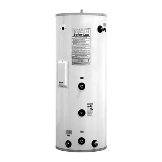
SolarCon solar water heater tank
Models:
NAS20053 Tank 50 gallon with lower coil and back up electric element
NAS20083 Tank 80 gallon with lower coil and back up electric element
NAS20123 Tank 119 gallon with lower coil and back up electric element
NAS20082 Tank 80 gallon with lower coil and top coil for boiler back up
NAS20122 Tank 119 gallon with lower coil and top coil for boiler back up
Technical characteristics
Tank materials:
Tank insulation:
Insulation thermal conductivity:
Tank external cover:
Anode rods:
Internal heat exchanger coil (lower):
Internal heat exchanger coil (top):
Maximum working pressure:
Testing pressure:
Temperature and pressure relief valve
Recommended maximum hot water temperature
Power requirements:
Power consumption:
Agency approval
Rev 3 7/18
REV1 8/08
Installation, commissioning and servicing instructions
Function
The solar water heater is designed with an internal coil and backup
electric heating element. A heating medium is passed through the
solar panels and internal coil as long as there is an adequate
temperature difference between the heating medium and stored water
in the tank. The internal coil is located as close to the bottom as
possible to facilitate the transfer of heat even at lower solar panel
temperatures.
During periods of water flow through the water heater, hot water is
drawn from the top of the heater and cold water is delivered to the
bottom of the tank (by a dip tube or bottom inlet). If the hot water
demand should exceed the solar heat input or there is an insufficient
temperature difference between the heating medium and stored
water, the heating element thermostat will activate the electrical
heating element for backup heat or boiler backup top coil.
Solar heat output from the internal coil will vary depending on outside
conditions and the temperature of the stored water.
NAS200 Series
porcelain coated steel
2" non-CFC foam
powder-coated steel (20-24 ga.)
2 each magnesium
1-1/2" x 30' (50 gallon)
1-1/2" x 36' (80, 119 gallon)
1-1/2" x 24'
210°F/150 psi max
240 VAC
UL listed
23500.03
R14
150 psi
300 psi
120°F
4.5 KW
Advertisement

Summary of Contents for Caleffi solar NAS20053
- Page 1 Models: NAS20053 Tank 50 gallon with lower coil and back up electric element NAS20083 Tank 80 gallon with lower coil and back up electric element NAS20123 Tank 119 gallon with lower coil and back up electric element...
- Page 2 WARNING INSTALLER RESPONSIBILITIES Improper installation, adjustment, alteration, Please read all instructions thoroughly service or maintenance can cause serious before installing or placing the heater into injury or property damage. Refer to this service. manual. assistance additional This unit must be installed by licensed or information, consult a qualified installer or authorized installers, or technical personnel service agency.
- Page 3 IMPORTANT SAFETY INSTRUCTIONS WARNING When using electrical appliances, basic safety precautions to reduce the risk of fire, electric shock, or injury to persons should be followed, including: 1. READ ALL INSTRUCTIONS BEFORE USING THIS WATER HEATER. 2. This water heater must be grounded. Connect only to properly grounded outlet.
-
Page 4: Table Of Contents
Table of Contents 1. Specifications ............5 2. -
Page 5: Specifications
COLD IN TO SOLAR (1" NPT) COLD IN (1" NPT) (1" NPT) (1" NPT) NAS20083, NAS20123 ONLY Figure 1: NAS20053, NAS20083, NAS20123 Figure 2: NAS20082, NAS20122 Table 1: Dimensions Model NAS20053 22´ ´ ⁄ ´ ´ 39 ⁄ ´ ´ 39 ⁄... -
Page 6: General Information
Loss Model Volume Solar/Boiler Solar/Boiler Solar/Boiler Rating (gal) & Backup Rating (gal) (gal) (ft of head) (gal/hr) (°F/hr) NAS20053 2.30/ - 11.78/ - 0.50/- NAS20083 2.76/ - 14.14/ - 0.60/- NAS20123 2.76/ - 14.14/ - 0.60/- NAS20082 2.76/1.84 14.14/9.42 0.60/0.40 NAS20122 2.76/1.84 14.14/9.42 0.60/0.40... - Page 7 SECTION II: GENERAL INFORMATION (cont.) TEMPERATURE CONTROL The solar water heater is equipped with a backup electrical heating element and adjustable thermostat. The thermostat is located behind the access cover on the side of the water heater. If the solar system cannot satisfy the user demand, the electric element will energize and heat the water until the thermostat is satisfied.
- Page 8 SECTION II: GENERAL INFORMATION (cont.) ANODE RODS The anode rod is used as a sacrificial element within the volume of the storage tank. The purpose of the magnesium anode rod is to protect the inside of the tank against corrosion. Anode rods should be inspected twice in the first year and at least yearly once a time interval for inspection has been developed.
-
Page 9: Pre-Installation
SECTION III: PRE-INSTALLATION LOCATION CAUTION This water heater must be located in an area where leakage of the tank, water line connections, or the temperature and pressure relief valve will not result in damage to the area adjacent to the water heater or to lower floors of the structure. When such location cannot be avoided, a suitable drain pan must be installed under the water heater. -
Page 10: Installation
SECTION IV: INSTALLATION WATER CONNECTIONS CAUTION This water heater incorporates fittings that contain a nonmetallic lining. DO NOT apply heat to these fittings when making sweat connections to the heater. Sweat tubing to an adapter before securing adapter to any fittings on water heaters. ALL PIPING SHOULD CONFORM TO LOCAL CODES AND ORDINANCES. - Page 11 SECTION IV: INSTALLATION (cont.) PIPING DIAGRAMS A piping diagram for a typical solar domestic water heating system based on an indirect water heater with electric heating backup is shown in Figure 3. Figure 3: Single tank system with electric backup Page 11...
- Page 12 SECTION IV: INSTALLATION (cont.) A typical two tank system is shown in Figure 4. The two tank system is mainly used where a conventional water heater is already installed. Figure 4: Two tank system with existing heater Page 12...
- Page 13 SECTION IV: INSTALLATION (cont.) Figure 5 shows an example of a domestic solar heating system based on an indirect water heater with two coils. The domestic water can be heated by the solar system as well as the boiler. Figure 5: Single tank system with boiler backup Page 13...
- Page 14 SECTION IV: INSTALLATION (cont.) Figure 6 shows a two tank system based on an indirect water heater and a solar water heater with electric back up. The stored water in the indirect water heater acts as a preheat to the space heating loop. Figure 6: Two tank with solar preheat to indirect boiler fired water heater Page 14...
- Page 15 SECTION IV: INSTALLATION (cont.) ELECTRICAL CONNECTIONS DANGER Confirm that all electrical connections are unpowered before installing or servicing electrical components/connections within the water heater. WARNING The water heater must be electrically grounded in accordance with local codes or, in the absence of local codes, with NFPA 70. Failure to properly wire electrical connections may result in serious physical harm.
-
Page 16: Operation
SECTION V: OPERATION THERMOSTAT TEMPERATURE ADJUSTMENT CAUTION The temperature setting on the heating element thermostat shall not exceed 160°F. Likewise, the solar controller potable water temperature setting shall not exceed 160°F. Install a thermostatic mixing valve or scald protection mixing valve at the outlet of the water heater to ensure greater control over water temperatures at the point of use. -
Page 17: Maintenance
SECTION VI: MAINTENANCE WATER PIPING On an annual basis, all piping should be checked for leakage at joints, shut-off valves, and unions. T&P RELIEF VALVE On an annual basis, the temperature and pressure relief valve should be checked for proper operation. -
Page 18: Troubleshooting
SECTION VII: TROUBLESHOOTING PROBLEM CAUSE SOLUTION No hot water at faucet ECO on thermostat tripped Determine cause of ECO trip (solar heat or electric element). Correct or replace as necessary. Reset thermostat (depress red button). Circulator does not operate Check power supply Replace as necessary Check solar controller Improper thermostat setting... -
Page 19: Parts List
SECTION VIII: PARTS LIST Table 7: NAS20053 Parts Part Description Immersion Well T&P Relief Valve Leak Detector 1" NPT x 3" Nipple J-Box Cover Drain Valve J-Box Cover (w/ conduit hole) Access Cover Hot Outlet with Anode Foam Dam Cover... - Page 20 SECTION VIII: PARTS LIST (cont.) 14 15 16 17 Table 7: NAS20053 Parts Part Description Immersion Well T&P Relief Valve Leak Detector 1" NPT x 3" Nipple J-Box Cover Drain Valve J-Box Cover (w/ conduit hole) Access Cover Hot Outlet with Anode...
- Page 21 SECTION VIII: PARTS LIST (cont.) Table 7: NAS20053 Parts Part Description Immersion Well T&P Relief Valve Leak Detector 1" NPT x 3" Nipple J-Box Cover Drain Valve J-Box Cover (w/ conduit hole) Access Cover Hot Outlet with Anode Foam Dam Cover...
- Page 22 NOTES Page 22...
- Page 23 NOTES Page 23...
- Page 24 Caleffi North America, Inc. 3883 W. Milwaukee Rd Milwaukee, WI 53208 Tel: 414.238.2360 Tel: 414.238.2366 Copyright © 201 Printed in the USA...
Need help?
Do you have a question about the NAS20053 and is the answer not in the manual?
Questions and answers