
Related Manuals for InoTec NEA

Summary of Contents for InoTec NEA
- Page 1 Mounting- and Operating Instructions Montage- und Betriebsanleitung NEA - ICU NEA - ICU Sicherheitstechnik GmbH...
-
Page 3: Table Of Contents
NEA - ICU Mounting and Operating Instructions NEA - ICU Montage- und Betriebsanleitung Inhalt Contents 1. Allgemeine Hinweise 1. General information 1.1. Symbolerklärung 1.1. Explanation of symbols 1.2. Haftung und Gewährleistung 1.2. Liability and warranty 1.3. Ersatzteile 1.3. Spare parts 1.4. - Page 4 NEA - ICU Mounting and Operating Instructions NEA - ICU Montage- und Betriebsanleitung 11.1.3. Freigabe 11.1.3. Release 11.1.4. Learnmode 11.1.4. Learn mode 11.2. Information 11.2. Information 11.2.1. Störung 11.2.1. Failure 11.2.2. Steuerteil 11.2.2. Controller 11.2.3. Leuchten 11.2.3. Luminaires 11.2.4. Ext. Komponenten 11.2.4.
-
Page 5: Allgemeine Hinweise
Von INOTEC gelieferte Batterien und Elektronikbauteile Batteries and electronic components supplied by INOTEC können an INOTEC zurückgegeben werden oder sind may be returned to INOTEC or should be disposed of in gemäß den nationalen Richtlinien und Vorschriften für accordance with the national guidelines and regulations... -
Page 6: Bedienungsanleitung
NEA - ICU Mounting and Operating Instructions NEA - ICU Montage- und Betriebsanleitung The device is only to be used for its intended purpose and only operated in perfect and undamaged condition. Das Gerät ist bestimmungsgemäß und nur im einwand- freien, unbeschädigten Zustand zu betreiben. -
Page 7: Produktbeschreibung
(diesel) generator. mittels eines (Diesel-) Generators. The NEA - ICU module can house up to 3 bus monitoring Das NEA - ICU Modul bietet die Aufnahme von bis cards with up to 99 addresses each. Freely program- zu 3 BUS-Überwachungskarten mit jeweils bis zu 99... -
Page 8: Funktionen
NEA - ICU Mounting and Operating Instructions NEA - ICU Montage- und Betriebsanleitung 4.1. Funktionen 4.1. Functions Folgende Funktionen sind serienmäßig enthalten: The following standard functions are included: • Eine Line Karte für 99 Leuchten • A line card for 99 luminaires •... -
Page 9: Systemschaltbild (Beispiel)
NEA - ICU Mounting and Operating Instructions NEA - ICU Montage- und Betriebsanleitung 4.2. Systemschaltbild (Beispiel) 4.2. System diagram (example) -
Page 10: Anschlußbelegung
Spannungsversorgung kontakt Störmeldekontakt 230~ 230~ Anschluss einer 24V DC Spannungsversorgung. Das Connection of a 24V DC voltage supply. The NEA SL Stromschleife SL Stromschleife Interner BUS Interner BUS NEA - ICU benötigt eine Versorgungsspannung von 24V - ICU needs 24V DC supply voltage. Voltage is supplied... -
Page 11: Nea Icu Im Kleinverteiler
Datenleitung 6. NEA–ICU in a small distribution board 6. NEA ICU im Kleinverteiler Small distribution board to install NEA-ICU as well as Kleinverteiler zum Einbau des NEA-ICU sowie der other system components. Versions as surface-, flush weiteren System Komponenten. Ausführungen... -
Page 12: Elektrischer Anschluss
6.2. Electrical connection 6.2. Elektrischer Anschluss The wiring at the NEA-ICU is done in the small distributor Die Verkabelung erfolgt bei der NEA-ICU im Installations- from above. The save mains is connected to the termi- kleinverteiler von oben. Das gesicherte Netz ist an den nals L, N and PE. -
Page 13: Zusätzliche Komponenten
NEA - ICU Mounting and Operating Instructions NEA - ICU Montage- und Betriebsanleitung 7. Zusätzliche Komponenten 7. Additional components 7.1. NE – ET 9-24 SV 7.1. NE – ET 9-24 SV Modul zur Versorgung und Überwa- Module for supplying and monitoring... - Page 14 NEA - ICU Mounting and Operating Instructions NEA - ICU Montage- und Betriebsanleitung Modul zur Einzelüberwachung von LLp Module for individually monitoring fluores- mit EVG oder AGL, Halogen Lampen und cent lamps with electronic ballast, standard LED Leuchten, mit Adressschalter zur bulbs, halogen lamps and LED luminaires, Leuchtenkodierung.
-
Page 15: Ne 4- Skü
NEA - ICU Mounting and Operating Instructions NEA - ICU Montage- und Betriebsanleitung 7.3. NE 4– SKÜ 7.3. NE 4– SKÜ Selbstlernendes Stromkreis Über- Self-learning (AC) circuit moni- wachungsmodul (AC) , in den Vari- toring module in two variants: anten 4x1,5A (Artikel-Nr.: 851 042) 4x1.5A (art. - Page 16 NEA - ICU Mounting and Operating Instructions NEA - ICU Montage- und Betriebsanleitung Technische Daten NE4/2-SKÜ-Modul.1: Technical specifications NE4/2-SKÜ module.1: Nennspannung UN: 230V 50/60Hz Rated voltage UN: 230V 50/60Hz Adressbereich: 0 - 96 (+1, +2,+3) Viererblöcke Address range: 0 - 96 (+1, +2,+3) blocks of four Max.
-
Page 17: Rif5
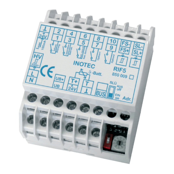
RIF5 und dem connection is used for communication NEA - ICU dient ein integrierter BUS- between the RIF5 and the NEA - ICU. Anschluss. Hierfür sind die Anschluss- Terminals “+24V”, “Masse” (ground) and klemmen „+24V“, „Masse“ und „BUS“... -
Page 18: Fernmeldetableau - Mtb
The remote mimic panel is connected to the RIF5 Das Fernmeldetableau wird an das RIF5-Modul und der NEA-ICU gem. nachfolgendem Schaltbild angeschlos- module and the NEA-ICU in accordance with the circuit sen. Die Leitungslänge darf bei einem Querschnitt von diagram below. The wire length may be a maximum of 500m with a cross-section of 0.5 mm². -
Page 19: Lsa
General lighting 850 008 230~ Up to 3 LSA 8.1 modules per NEA - ICU can be connected Je NEA - ICU sind bis zu 3 LSA 8.1-Module an den to the device bus. The LSA 8.1 has 8 electrically isolated Gerätebus anschließbar. -
Page 20: Lsa 3.1
NEA - ICU Mounting and Operating Instructions NEA - ICU Montage- und Betriebsanleitung 7.7. LSA 3.1 7.7. LSA 3 Es können maximal 8 LSA 3-Module je Controller ange- A maximum of 8 LSA 3 modules can be connected per schlossen werden. Jedes Modul besitzt drei Eingangska- controller. -
Page 21: Dpü
NEA - ICU Mounting and Operating Instructions NEA - ICU Montage- und Betriebsanleitung 7.8. DPÜ/B.2 7.8. DPÜ/B.2 Zur Überwachung der Netzspannung an den Unterver- The DPÜ/B.2 modules are installed directly onto the sub- teilern der Allgemeinbeleuchtung werden die DPÜ/B.2- distribution boards to monitor the supply voltage of the Module direkt in den Unterverteiler eingebaut. - Page 22 NEA - ICU Mounting and Operating Instructions NEA - ICU Montage- und Betriebsanleitung Netzausfall UV Netzausfall Sub-db failure Mains failure F2 F3 F2 F3 DPÜ / B.2 DPÜ / B.2 890 417 890 417 INOTEC INOTEC 0 Min 5 Min...
-
Page 23: Bedienung
NEA - ICU Mounting and Operating Instructions NEA - ICU Montage- und Betriebsanleitung 8. Bedienung 8. Operation 8.1. Steuereinheit 8.1. Controller 8.1.1. Display 8.1.1. Display The status display In der Mitte angeord- Current date and time are displayed in is located in the net befindet sich die the header. -
Page 24: Menüstruktur
NEA - ICU Mounting and Operating Instructions NEA - ICU Montage- und Betriebsanleitung 22.08.2008 15:30 Status 9. Menüstruktur 9. Menu structure Funktionen Information Programmierung Funktionen Funktionen Information Programmierung Start FT Störungen Steuerteil Konfig. laden Blockieren Steuerteil Datum+Uhrzeit Konfig. speichern Software Version... -
Page 25: Programmierung
NEA - ICU Mounting and Operating Instructions NEA - ICU Montage- und Betriebsanleitung 11. Programmierung 11. Programming 11.1. Funktionen 11.1. Functions Im Menü „Funktionen“ gelangen Sie mittels Bestäti- Press the confirmation key in the “Functions” menu gungstaste in ein Untermenü. Dort befinden sich to access a sub-menu where you will find functions Funktionen, um einen „Funktionstest“... -
Page 26: Blockieren
NEA - ICU Mounting and Operating Instructions NEA - ICU Montage- und Betriebsanleitung Datum Uhrzeit Date Time Start FT Start FT Im Display wird der jeweilige Gerätestatus dargestellt. The status of each device is shown on the display. In case Sofern eine Leuchtenstörung vorliegt, wird diese mit... -
Page 27: Freigabe
NEA - ICU Mounting and Operating Instructions NEA - ICU Montage- und Betriebsanleitung • Controller eigenes Menü • Controller‘s own menu • Fernschalter • Remote switch • INOView • INOView • Modbus • Modbus • HTML-Seite • HTML page Die Freigabe kann nur über die Schaltstelle A device must be released at the same switch erfolgen, über die das Gerät blockiert wurde. -
Page 28: Learnmode
Hier können die Stromreferenzwerte der „End- stromkreise“ oder „Einzelleuchten“ eingelernt werden. 11.1.4.1. Complete 11.1.4.1. Komplett The permissible current reference values for all NEA Im Learnmode „Komplett“ werden die zulässigen Strom- monitoring module are determined in Learn mode referenzwerte aller NEA Überwachungsmodule ermittelt. - Page 29 NEA - ICU Mounting and Operating Instructions NEA - ICU Montage- und Betriebsanleitung Komplett Complete Line / Adr. Line/Add. Line 1/2/3 Line 1/2/3 (OK) (Abbruch) (OK) (Cancel) Learnmode Learn mode Line 1/2/3 Line 1/2/3 Learnmode Learn mode Learnmode Learn mode Sobald der „Learnmode“...
-
Page 30: Information
NEA - ICU Mounting and Operating Instructions NEA - ICU Montage- und Betriebsanleitung Komplett Complete Line / Adr. Line/Add. Linie: Line: Adresse: Address: Learnmode Learn mode Line 1 - Adr. 1 Line 1 - Add. 1 (OK) (Abbruch) (OK) (Cancel) -
Page 31: Störung
NEA - ICU Mounting and Operating Instructions NEA - ICU Montage- und Betriebsanleitung 11.2.1. Störung 11.2.1. Failure Die Störungen, die der Controller in der „Line“, an den The system displays failures of relevant luminaire ad- jeweiligen Leuchtenadressen erkannt hat, werden ange- dresses detected by the controller in the “line”. -
Page 32: Leuchten
NEA - ICU Mounting and Operating Instructions NEA - ICU Montage- und Betriebsanleitung 11.2.2.2. IP Adresse 11.2.2.2. IP address Die IP Adresse ist in dem Untermenü „IP“ hinterlegt. The IP address is stored in the “IP” sub-menu. Use the Mittels der Navigationstasten ist über den Pfad der navigation keys to navigate through Information –... - Page 33 NEA - ICU Mounting and Operating Instructions NEA - ICU Montage- und Betriebsanleitung Information Leuchten Belegung Information Luminaires Assignment Line 1 Line 1 Line 2 Line 2 Line 3 Line 3 1: § § § § o o o o o o 1: §...
-
Page 34: Ext. Komponenten
NEA - ICU Mounting and Operating Instructions NEA - ICU Montage- und Betriebsanleitung wählt wurde, kann der jeweilige Statusbericht im Display evant status report is displayed. Use the navigation keys eingesehen werden. Durch Scrollen mittels der Navigati- to scroll through this menu for information about oper- onstasten ist es möglich, in diesem Menü... -
Page 35: Prüfbuch
NEA - ICU Mounting and Operating Instructions NEA - ICU Montage- und Betriebsanleitung 11.2.5. Prüfbuch 11.2.5. Logbook 11.2.5.1. Prüfbuch anzeigen 11.2.5.1. Show logbook Wählen Sie im Menü Information die Rubrik „Prüfbuch“ Select “Logbook” in the Information menu. Confirm aus. Durch Bestätigen mit der Eingabetaste gelangen Sie with the Return key to open the sub-menu, where you in das Untermenü, in dem mittels Navigationstasten zwi-... -
Page 36: Programmierung
NEA - ICU Mounting and Operating Instructions NEA - ICU Montage- und Betriebsanleitung Anzeigen Show Löschen Delete Prüfbuch Delete Löschen? Logbook? oder Prüfbuch wird Deleting gelöscht Logbook 11.3. Programmierung 11.3. Programming 11.3.1. Steuerteil 11.3.1. Controller 11.3.1.1. Datum + Uhrzeit 11.3.1.1. Date + Time Wählen Sie im Menü... -
Page 37: Programming
NEA - ICU Mounting and Operating Instructions NEA - ICU Montage- und Betriebsanleitung select individual information columns. Settings can be tasten einzelne Informationsspalten angewählt changed with the navigation keys werden. Mit den Navigationstasten können die Einstellungen verändert werden. Thursday Donnerstag 28/05/2015 28.05.2015... - Page 38 NEA - ICU Mounting and Operating Instructions NEA - ICU Montage- und Betriebsanleitung OOOO OOOO Input Password already Eingabe Bereits festgelegtes specified Passwort OOOO OOOO > Password < > Passwort < 11.3.1.4. Defaultparameter 11.3.1.4. Default parameters In dem Menü „Defaultparameter“ ist es möglich, den The controller can be reset to factory setting in the “De-...
-
Page 39: Inotec Anlagenkonfigurator
übersichtliche Einsicht und Bearbeitung new configurations to the connected controller. Configu- bestehender sowie neu zu erstellender Konfigurationen rations can be transferred from PC to relevant NEA - ICU des angebundenen Controllers. Konfigurationen können by FTP (File Transfer Protocol) or USB flash memory. The... -
Page 40: Ftp (File Transfer Protocol)
NEA - ICU Mounting and Operating Instructions NEA - ICU Montage- und Betriebsanleitung Belegung: Assignment: In der Geräteeinstellung angemeldete „Lines“ sind in “Lines” set up in “Device settings” must be programmed dem Menü „Belegung“ bis hin zur Leuchtenebene zu down to luminaire level in the “Assignment” menu. Pa- programmieren. -
Page 41: Visualisierung (Inoview)
RTG-Karte, die am „Line 3“ (RTG passiv) entsprechend zu konfigurieren ist. Sofern der NEA - ICU an die INOView angebunden wird, If the NEA - ICU is connected to INOView, “Direct network ist die Kommunikationsschnittstelle „direkte Netzwerk- connection” must be selected as the communication verbindung“... -
Page 42: Usb
Steuerteil und der INOTEC Konfigurationssoftware and the INOTEC configuration software. A folder struc- zu gewährleisten, ist diese Anordnung zwingend einzu- ture has been specified for INOTEC’s USB flash memory halten. Um die verschiedenen Dateiformate jeweiliger to ensure clarity and uniformity of the various file Anwendungen übersichtlich und einheitlich zu gestal-... -
Page 43: Dateiformate
NEA - ICU Mounting and Operating Instructions NEA - ICU Montage- und Betriebsanleitung 11.6.2. Dateiformate 11.6.2. File formats Die Vergabe der Dateinamen ist auf 8 Zeichen begrenzt. File names must not exceed 8 characters. These charac- Diese Zeichen dürfen lediglich aus Großbuchstaben und ters must be capital letters or numbers. -
Page 44: Konfiguration Speichern
NEA - ICU Mounting and Operating Instructions NEA - ICU Montage- und Betriebsanleitung System Neustart System restart Nach dem Neustart kann das USB Speichermedium aus After restart, the USB flash memory can be removed dem Controller entfernt werden. from the controller. -
Page 45: Störungsinfo Speichern
NEA - ICU Mounting and Operating Instructions NEA - ICU Montage- und Betriebsanleitung OK Konfiguration OK, configuration erzeugt produced 11.6.5. Störungsinfo speichern 11.6.5. Save failure information Um Einträge der Störungsinfo auf dem USB Speicher- medium zu sichern, ist die Auswahl der „Störungsinfo“... -
Page 46: Prüfbucheinträge Speichern
11.6.7. Update Mittels einem Softwareupdate ist es möglich, das NEA - The NEA - ICU can be updated to a new firmware version. ICU mit einer neuen Firmware-Version zu versorgen. Mit The new firmware is easily loaded onto the device using einem USB-Stick kann die neue Firmware einfach auf das a USB stick. -
Page 47: Save Logbook Entries
NEA - ICU Mounting and Operating Instructions NEA - ICU Montage- und Betriebsanleitung 11.6.7.2. Bootloadermodus starten 11.6.7.2. Start Bootloader mode Um das Softwareupdate durchzuführen, ist zunächst der To update the software, connect the USB stick to the USB Stick in den USB Port des Controllers ein zu stecken. - Page 48 NEA - ICU Mounting and Operating Instructions NEA - ICU Montage- und Betriebsanleitung Lade Firmware Loading firmware !Achtung! !Caution! Datenträger data carrier !Nicht entfernen! !Do not remove! Firmware geladen Firmware loaded Neustart Restart...
-
Page 49: Inoweb (Html / Web Browser)
To do ser dargestellt werden. Dazu wird der NEA - ICU in ein this, the NEA - ICU must be connected to a local network. lokales Netzwerk eingebunden. A standard web browser is used to load the INOWeb user Die INOWeb Oberfläche ist über einen Standard... -
Page 50: Allgemeine Informationen
NEA - ICU Mounting and Operating Instructions NEA - ICU Montage- und Betriebsanleitung dem Anwender folgende Funktionen zur Verfügung: following functions: • Funktionstest starten • Start function test • Blockieren • Block • Freigeben • Release Durch einen Mausklick auf eine der Schaltflächen kann Click on one of the buttons to start the relevant function. -
Page 51: Leuchteninformationen
NEA - ICU Mounting and Operating Instructions NEA - ICU Montage- und Betriebsanleitung des Netzausfalles nicht in Funktion. emergency lighting will not work in the event of a mains failure. Eine Blockierung des Controllers kann über The controller can be blocked from various switch verschiedene Schaltstellen erfolgen. -
Page 52: Glossar
NEA - ICU Mounting and Operating Instructions NEA - ICU Montage- und Betriebsanleitung 13. Glossar 13. Glossary Non-maintained light Bereitschaftslicht Emergency lighting / circuit is switched off Notleuchte/Stromkreis ist im Netzbetrieb in mains operation and is switched on in ausgeschaltet und wird bei Notbetrieb emergency operation. - Page 53 NEA - ICU Mounting and Operating Instructions NEA - ICU Montage- und Betriebsanleitung Geschaltetes Dauerlicht Switched maintained light Betriebsart für à Endstromkreise oder Mode for à final circuits or luminaires in Leuchten im Endstromkreis, welche über the final circuit that are switched with the à...
- Page 54 Einzelleuchtenüberwachungskarte zum Individual luminaire monitoring card Einbau in INOTEC NEA - ICU. An diesen that is installed in the NEA - ICU. A maxi- Strang können max. 99 NE-SV-Überwa- mum of 99 NE-SV monitoring modules or chungsmodule oder Leuchten mit NE/ luminaires with NE/SV function monitors SV-Funktionskontrolle über eine 2-adrige,...
- Page 55 NEA - ICU Mounting and Operating Instructions NEA - ICU Montage- und Betriebsanleitung NE – SV / - Modul/L NE – SV / module/L Einzelüberwachungsmodule zur Einzel- Modules for individually monitoring überwachung von LLp, AGL und Halogen- fluorescent lamps, standard bulbs, and...
- Page 56 NEA - ICU Mounting and Operating Instructions NEA - ICU Montage- und Betriebsanleitung Prüfbuch Logbook Dokumentation aller auftretenden Ereig- Electronic or manual documentation of all nisse und Meldungen des Notlichtgerätes. events and messages relating to the emer- Kann elektronisch oder manuell geführt gency lighting device.
- Page 57 NEA - ICU Mounting and Operating Instructions NEA - ICU Montage- und Betriebsanleitung Index Index Symbole Symbole Ausgangsklemme Ausgangsklemme Belegung 30,31,32,39 Belegung 30,31,32,39 Blockiert 11,24,50 Blockiert 11,24,50 Bootloader 45,46 Bootloader 45,46 BUS-Anschluss 7,8,16 BUS-Anschluss 7,8,16 Dateiname 43,44,45 Dateiname 43,44,45 Defaultparameter...
- Page 58 NEA - ICU Mounting and Operating Instructions NEA - ICU Montage- und Betriebsanleitung Programmierung 8,11,14,16,23,34,37 Programmierung 8,11,14,16,23,34,37 Prüfbuch 7,24,33,34,45,49,54 Prüfbuch 7,24,33,34,45,49,54 38,54 38,54 RTG-BUS RTG-BUS RTG-Karte 11,40 RTG-Karte 11,40 RTG passiv RTG passiv Softwareversion Softwareversion Statusanzeige Statusanzeige Steuerteil 29,30,34,39,41,51,55 Steuerteil 29,30,34,39,41,51,55 Störung...
- Page 59 NEA - ICU Mounting and Operating Instructions NEA - ICU Montage- und Betriebsanleitung...
- Page 60 INOTEC Sicherheitstechnik GmbH Am Buschgarten 17 59 469 Ense Germany +49 29 38/97 30-0 Fax +49 29 38/97 30-29 info@inotec-licht.de www.inotec-licht.de 708 215 B 09/2016 Sicherheitstechnik GmbH...
Need help?
Do you have a question about the NEA and is the answer not in the manual?
Questions and answers